I am convinced that modern embedded framework development is less about engineering and more about surviving a sequence of silently laid traps. I spent this past weekend trying to bring up code in src/radio on the new M5Stack Tab5—featuring the dual-architecture marriage of an ESP32-P4 and an ESP32-C6 Wi-Fi co-processor.

What should have been a straightforward exploration of a brand-new RISC-V application processor instead devolved into a multi-layered diagnostic nightmare. By Sunday night, I wasn’t just debugging code; I was literally jump-starting a stone-dead lithium-ion battery on a benchtop supply because the vendor’s Board Support Package (BSP) had silently signed its death warrant.

If you enjoy detective stories where the murder weapon is a rogue I2C initialization sequence, pull up a chair.

Layer 1: The Kconfig Mirage and the Missing Environment Variable

The fun starts before you even talk to hardware. When trying to compile the espressif__esp_hosted component to let the P4 talk to the C6, the toolchain grinds to a halt with a spectacular piece of technical gaslighting:

managed_components/espressif__esp_hosted/host/api/include/esp_hosted_config.h:59:2:
error: #error "Unknown Slave Target"

Why doesn’t it know what an ESP32-C6 is? Because espressif__esp_wifi_remote relies on a specific environment variable ($ESP_IDF_VERSION) to locate its own target definition files.

If you are running ESP-IDF 5.5.4, the native export script dutifully sets IDF_VERSION=5.5.4. But the component’s internal CMake logic is hardcoded to look for a truncated $ESP_IDF_VERSION=5.5. If that exact variable isn’t present, the build system doesn’t throw a warning. It doesn’t halt. It just silently skips sourcing the slave target definitions. The component ships broken out of the box.

The Canonical Recipe: You must manually export ESP_IDF_VERSION=5.5 before running idf.py build.

Layer 2: The Silicon Revision Time Machine

Once the build system stops hallucinating, you run into the next silent trap: the ESP-IDF defaults the ESP32-P4 to silicon revision 3.1.

This is fascinating because revision 3.1 hasn’t even shipped yet. The M5Stack Tab5 uses revision 1.0.

If you try to fix this in sdkconfig.defaults, you’ll quickly learn that Kconfig choice menus are notoriously sticky. Even with the right value in defaults, the choice will silently revert to the toolchain’s winner on every target set. Furthermore, the bootloader is built as an ExternalProject, meaning it doesn’t cleanly propagate sdkconfig changes through normal build invalidation.

To break out of the time machine and talk to the hardware currently sitting on your desk, you have to find the master boolean override: SELECTS_REV_LESS_V3=y in your sdkconfig.defaults.

When you build, check your actual active config:
grep CONFIG_ESP32P4_REV_MIN_100 sdkconfig

Only when that search returns =y (rather than being absent or # NOT SET) are you actually done with the toolchain and talking to the Rev 1.0 hardware.

Layer 3: The Wi-Fi Stub Illusion and the Missing Link

The ESP32-P4 has absolutely no Wi-Fi silicon on board. Yet, calling esp_wifi_init() runs flawlessly. No error codes, no diagnostics—just an empty void of silent zeroes returning from your APIs.

In our early efforts to see a firmware version on the C6 co-processor and read its MAC address, we hit this wall of zeroes. We initially misdiagnosed it as a transient power rail issue, assuming the C6 wasn’t waking up in time. To make sure it was awake, we reached into the BSP and enabled the Wi-Fi feature explicitly:

// Initialize IO Expander 1 (which hosts C6 power enable)
bsp_io_expander1_init();

// Power on the ESP32-C6 Wi-Fi co-processor via the BSP
ESP_LOGI("WiFiSystem", "Enabling ESP32-C6 Wi-Fi co-processor power...");
esp_err_t wifi_en_err = bsp_feature_enable(BSP_FEATURE_WIFI, true);

Spoiler: power wasn’t the issue. The real reason the C6 was acting like a ghost was a software missing link. To stop ESP-IDF from linking its dummy stubs and actually route the Wi-Fi API calls to the physical C6, you have to ensure esp_hosted is properly declared and that CONFIG_SLAVE_IDF_TARGET_ESP32C6 is actively selected. Once we fixed the component linking, the C6 woke up, returned a real MAC address, and we moved on.

But little did we know, that vestigial snippet of power-enable code we added during our misdiagnosis was hanging on the wall like Chekhov’s gun, waiting to fire in the second act.

Layer 4: The Silence of the Chargers

A day later, the real mystery began. I unplugged the Tab5 from my development host, and the device instantly died.

I pulled out the multi-meter. The battery is reading 0.0V. Not low. Not flagging. Monty Python parrot dead. I hooked it up to the benchtop supply, cranked it to 7.5V with a few hundred mA, and effectively jump-started the cells.

(Sidebar: If you find yourself doing this, limit your current and touch the cell occasionally to monitor its temperature. Having previously set a Li-Ion battery ablaze—a smell that never quite leaves your workspace—I was concerned, but apparently not concerned enough to not do it.)

The jump-start was successful! I did a quick test, removed the cable, and watched the device “coast” on battery for a few minutes. This gave me a false sense of security. I figured the battery was just having a bad day, and that leaving it plugged into my host for further development would charge it responsibly—much like joyriding in a car after jump-starting it to heal the battery with a charge from the alternator.

Demo time! Unplug from the computer… instant death. Back to 0.0V.

Naturally, it was time to look at the telemetry. Espressif has APIs for charging states and voltages, but in keeping with current traditions, they aren’t actually implemented for this board/chip combo. I glanced at the schematics, saw a plain old INA226 monitoring the rails, knocked out some quick boilerplate driver code, and read the registers directly.

The data was immediately whackadoodle:

  • With the battery removed, it read a floating phantom voltage of 1.08V.
  • Plug the battery in, and it drops to 0.
  • The isCharging bit was completely inverted because—in a stunning display of hardware engineering—they hooked the INA226 up backward.

But even after accounting for the backward bit, the chip was reading 0mA of charge current. Why? Because there was 0V being delivered to the battery terminals. I beat the local I2C I/O expander at address 0x44 with the biggest stick possible, forcing the charge enable (CHG_EN) bits high:

// Expander 0x44: CHG_EN, CHG_STAT, QC_EN, PWROFF, USB5V, WLAN_PWR.
// OUT_SET first: CHG_EN(7)=1, nCHG_QC_EN(5)=0 (QC enabled), WLAN_PWR_EN(0)=1.
write_expander_reg(bus, 0x44, IOEXP_REG_OUT_SET, 0b10000001); // CHG_EN (bit 7) = 1

// Verify CHG_EN actually landed
uint8_t out_set_readback = read_expander_reg(bus, 0x44, IOEXP_REG_OUT_SET);
ESP_LOGI(HW_TAG, "Expander 0x44 OUT_SET readback: 0x%02x", out_set_readback);

The register readback confirmed bit 7 was high. Yet, the battery terminals remained completely cold.

The Whodunit Revealed: Death by Global Reset

Here is the anatomy of the crime. Remember that initialization code from Layer 3?

Deep inside managed_components/espressif__m5stack_tab5/src/bsp_feature_en.c, the function bsp_feature_enable(BSP_FEATURE_WIFI, true) invokes bsp_io_expander1_init(). This internally configures the PI4IOE5V6408 driver for the I2C expander at 0x44.

The upstream driver’s initialization sequence issues a global reset to the expander chip.

A global reset reverts every single register on the multiplexer to power-on defaults. Every pin is wiped back to an input, and the output registers are totally zeroed out. This means every time the BSP touches the Wi-Fi feature, it silently obliterates the CHG_EN bit bit that tells the hardware charger IC to feed the battery. But it gets worse. That expander chip is the central nervous system for the board’s power. By resetting it, enabling the Wi-Fi using the vendor’s documented interface, the Wi-Fi initialization sequence is also acting as a serial killer for the USB 5V output, the Quick Charge negotiation, and the main system power-off latch.

[Your Code] -> Asserts CHG_EN (Battery tries to live
      ↓
[BSP Wi-Fi Init] -> Global Reset to Expander 0x44 -> CHG_EN = 0 (Silent Death)

The Post-Mortem Fixes

After a full day in this architectural loop of despair, the fix required two distinct steps:

  1. Purge the vestigial BSP Wi-Fi code. Getting rid of bsp_feature_enable stops the hardware expander from resetting itself into oblivion.
  2. Sanitize the telemetry logic. Invert the backward current direction on the INA226. Ignore any phantom voltage under 1.06V. Treat each divisor as exactly 1.25mV, and bypass any broken external scalers.

With those changes committed, reality has returned to the workbench. The telemetry now shows a responsible, slowly rising battery voltage, a couple hundred mA of charge current that drops cleanly to zero when full, and a steady 200mA discharge when the dual CPUs and Wi-Fi are cooking with the screen off. A full charge sits at 8216mV—spot-on for a 2S 18650 pack.

I’ve committed the fixes, documented the insanity in sdkconfig.defaults and AGENTS.md, and we will never lose this ground again. But let this be a lesson: if your ESP-IDF project is behaving weirdly, check your environment variables—and then check if your toolchain is trying to fire-sale your lithium infrastructure.

The TL;DR: ESP-IDF 5.5 / Tab5 Survival Checklist

To tie a bow on this murder mystery, here is the master punchlist for the next poor soul trying to get Wi-Fi working on an ESP32-P4 without accidentally executing their battery:

  1. The Environment Variable Penalty: You must export ESP_IDF_VERSION=5.5 before every single invocation of idf.py. If you forget, the build system detects the shift from 5.5 back to 5.5.4, assumes you are changing toolchains, and cheerfully triggers a 2,500-file recompile to punish you.
  2. The Component Linkage: Adding the espressif__esp_hosted component to your build isn’t enough. You must explicitly enable it in the configuration (CONFIG_SLAVE_IDF_TARGET_ESP32C6=y). If you skip this, the framework silently links the dummy stubs, leaving you staring at a wall of zeroes.
  3. The Silicon Revision Trap: Avoid the attractive nuisance of trying to manually set CONFIG_ESP32P4_REV_MIN_0, CONFIG_ESP_REV_MIN_FULL, or related variables. They are deeply intertwined, and Kconfig will stubbornly overwrite your choices with its own broken defaults. You must assert the master boolean (CONFIG_ESP32P4_SELECTS_REV_LESS_V3=y) to force it to respect Rev 1.0 hardware.
  4. The Battery Assassin: Never call bsp_feature_enable(BSP_FEATURE_WIFI, true). The resulting global I2C reset will nuke your battery charger, your USB 5V output, and your system power-off latch in one fell swoop.

This is an article I’m updating as I experience this device.
June 17. First update.
June 18, Hello World added.
Aug 16, 60 GPIOs. None free!

I was lucky enough to score one of the first Espressif S31-Korvo development boards. The board itself is a bit nifty as far as SBCs go, but let’s be honest, this is a development vehicle for their new darling of the development the ESP32-S31. It’s available from Espressif’s store on Aliexpress. (Brace yourself: shipping commands a premium, but I had five-day delivery to the U.S. once it shipped.) As an explorer, I won’t repeat the data sheet here, but I’ll focus on surprising things I learn along the way.

Espressif’s Naming

As with their entire lineup, it’s designed to confuse people. Here’s my take on it.

The chip is ESP32-S31 . That’s the 8 mm square part that most peole will never actually see.  When we talk about “ESP32-S31”, we’re mostly talking about the chip that’s inside the chip that’s inside the module that’s on a board. Whew! Matryoshka dolls all the way down

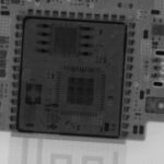
Most users will never really see the ESP32-S31. If you peek inside the module, you’ll find the actual core is packaged on the wafer next to a few passives and flash ROM in the upper left corner here. The PSRAM is stacked directly atop the main SOC silicon, harder to see in this picture from 3DPhotonix. (This is an ESP32-S3, but most modern modules follow this basic model.)

ESP32-S3 XRay
ESP32-S3 XRay

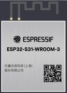
What most people will commonly call the “ESP32-S31” is the module. The module (usually) includes an antenna or antenna connector, the flash, and a handful of passives to stabilize the whole thing. That’s the familiar postage-stamp-sized thing with all the pins we see:

ESP32-S31 Module
ESP32-S31 Module

Espressif’s product line breaks down approximately like

  • ESP32-H: (Examples: ESP32-H2, ESP32-H4) Low-power. Targets IoT with funky radios
  • ESP32-C: (Ex ESP32-C2, ESP32-C3) – more performance, high-volume, single-core, simple connectivity
  • ESP32-S (Ex.: ESP32-S2, ESP32-S3, ESP32-S31:  high performance, rich networking connectivity, 
  • ESP32-P (Currently ESP32-P4): High performance, high connectivity for video (camera, screen) applications.

Notice how this categorization doesn’t really say what CPU core is used. Older parts are Xtensa; newer parts are RISC-V. Some people will scream that the ESP32-S31 shouldn’t cluster with ESP32-S3 because it’s RISC-V instead of XTensa. It’s probably borderline to say that it coudlhave been ESP32-S4 to help searchability, but I don’t pick the names.

ESP32-S31: Defined and Product Positioning

In product positioning, the ESP-S31 seems aimed to generationally replace the original ESP32 and the ESP32-S3, which featured higher performance, but notably misses a few key peripherals like legacy Bluetooth (adoption of audio BLE hasn’t really happened) and turns the knob to eleven for performance. 

It’s positioned a bit below the ESP32-P4 for performance, targeting “a maximum of 320 MHz,” while the ESP32-P4 promised 400Mhz. (To my great annoyance, they shipped a ton of what was essentially engineering samples that didn’t meet the published specs. They were 360 MHz parts, but they only changed the datasheets to reflect this after they’d shipped for about two years.) It doesn’t feature the MIPI interface, but it adds Gigabit Ethernet and, critically to a lot of people, a full collection of radios.

The reality of choosing chips in commercial products is that every gate and every pin for a feature you don’t need is cost wasted, so the ideal SOC has everything you need and nothing else. For most hobbyists or low-quantity development, it’s usually the case to standardize around a chip a little more featureful than you need, but at a budget that you don’t weep about. For example, I use ESP32-S3 in most of my projects, whether I need CANBus, err, TWAI, or not just because standardizing around a single toolchain is easier than trying to save a coin or two on a less featured part. Could I use some less expensive WCH32V part instead of an ESP32-C3 when I don’t need WiFi? Sure. But when ESP32-C3 Nanos are two bucks (often $1 on sale as a filler item), it’s easier to just keep them on hand as my goto low-end device. When I need a bit more chops, I waffle between the ESP32-S3 Supermini when size counts or an ESP32-S3 N8R16 DevKit-C clone when I need more pins or more RAM. I don’t stock the N4R2 variations that are $0.35 cheaper…because I’m a baller like that.

ESP32-S3 seemed logical to replace the original 2016 ESP32, but several omissions made that impractical. Notably, it brings back Classic Bluetooth, making it usable for audio Bluetooth. The original ESP32 had two DAC channels on GPIO25 and GPIO26. ESP32-S3 lacked DAC support completely. ESP32-S31 gives us two 10-bit and two 12-bit DACs. ESP32-S3 also surrendered SDIO slave mode and the Ethernet MAC. This meant that ESP32-S3 wasn’t just a slam-dunk replacement for the older part. ESP32-S31 “fixes” those omissions and adds many new internal peripherals.

ESP32-S31 adds (back) all of those. It raises the gigabit Ethernet option to a 1 Gbps interface. It adds WiFi 6 (probably borrowing from the ESP32-C6), which gives the reliability of 802.11AX for better handling in crowded WiFi environments. We go from 45 to 60 GPIOs, though in reality that number will never actually be available to everyone. We gain two more UARTs, raising the number to five. We gain three SPI controllers, reaching seven. We gain an I2C controller, giving us three. We get another LED PWM controller, giving us two. ESP32-S3 supported a maximum of 32MB of PSRAM, though only 2, 8, and 16MB were common. ESP32-S31 raises maximum addressable flash and PSRAM to 256MB and64 MB, respectively.

We also see peripherals that we’ve seen in newer models ESP32-C6 or ESP32-P4 added, like the advanced JPEG and 2D-DMA hardware acceleration for video, and a second generation touch sensor. 

  • PARLIO is for high-speed, parallel data streaming. It is highly optimized for routing parallel camera inputs or high-resolution displays.
  • BitScrambler is a new alternative to RMT and is reminiscent of the PIO engines in Raspberry Pi Pico. It’s a hardware programmable state machine located within the DMA path. to arbitrarily reorder, mask, or shift incoming/outgoing bits on the fly during data transfers, making it highly useful for direct generation of protocols (like WS2812 LEDs) or out-of-order data alignment without loading the CPU.
  • A hardware JPEG codec offloads CPU for rapid encoding and decoding.
  • The Pixel Processing Acelerator, PPA, is a dedicated 2D graphics accelerator used for image scaling, color space conversion, and basic 2D operations, significantly boosting GUI and HMI performance.
  • ASRC adds Hardware-level audio processing block designed to adjust digital audio sampling rates on the fly. 
  • The new radios get all the IoT buzzwords: WiFi 6, Thread and Zigbee

It’s like Espressif looked around their module collection that they already had IP for and turned on all the #ifdfefs. Kitchen sink included!

Presumably they learned a lesson from the P4 fiasco and are more forthcoming that this is currently an engineering sample part and they’re strongly branding it as such. To their credit, they’re providing very complete developer kits, a hundred-page datasheet and extensive technical reference manual.

Now as I write this, these are new. Very very new. They’re for developers to bring up their own products and evaluate for their own designs. There are rough spots.

  • ESP-IDF for ESP32-S31 is under active development. There was some support in 5.5, but yu probably want to follow master. (Observe that just changing the doc tage to ‘latest’ makes the page disappear.) It will probably be ESP-IDF 6.1 where S31 lands “for realsies”. I’d expect common operations (wiggling GPIO pins, std::cout, etc.) to land before every detail of every periphal described above is fully accessible.
  • The Espressif Forum has a section dedicated to ESp32-S31.
  • ESP-Arduino32 Is simply not ready. It’ll be Arduino4 and the patches being proposed so far make it clear that we’re in for another “dot oh” rough transition, as we incurred during the 3.0 transition a few years ago, though it looks less radical. They’ll need to land IDF 6.1 and then roll in new ESP32-S31 support for Arduino.

ESP32-S31: Need for Speed.

It’s designed to be fast. (Ahem. See later note on the difference between design and implementation…) Clock speed doesn’t tell the whole story. (Never has…Remember when a 60Mhz Pentium would beat up your 66Mhz 486 and take its lunch money? Well, it’s 1989 all over again.)

Architecture ESP32-S3 ESP32-S31 ESP32-S4
Max Clock Frequency 240 320 400
CoreMark/Mhz 5.54 6.86 6.228

Total CoreMark/td>

1329.92 2195.20 2491.20

CoreMark is an industry standard measure of performance in microcontrollers. Think of it as a modernized Dhrystone, but complicated enough that optimizers don’t recognize it and special-case the source code. The number in this table is “6.86”. It’s faster per clock cycle than the flagship ESP32-P4 (we assume it benefits from another three years of tuning) and it’s way faster per clock cycle than the Xtensa LX7 core in an S3 (which was alrealdy faster than the LX6 in original ESP32.) So we could expect a 240 MHz ESP32-S31 (no such configuration exists as of this writing) to be about 23.8% faster on compute-bound tasks than the familiar ESP32-S3, just by nature of rebuilding your source for it.

Development Boards

In this pre-launch state, there are two boards available from Espressif. The launch boards exist to help developers build their actual products. It lets us test code generation, built tooling, prototype with breadboards or connected breadbords, and generally decouple our own hardware and software development from the needs of the SoC.

ESP32-S31-Function-CoreBoard (I don’t know why “function” is in that name, but it is…) is the kind of obvious entrypoint. It’s inexpensive for even a hobbyst at about $25UD. This isn’t the board I have, so this isn’t discussed further.

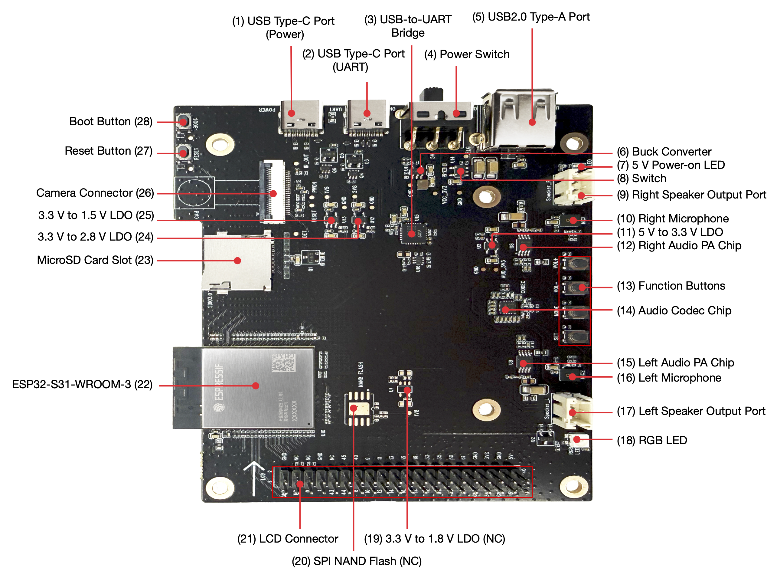
ESP32-S31-Korvo-1 (I also don’t know if the “-1” is part of the name, but it is…) is a fully-featured board with electronics approximately similar to that of an Amazon Echo type of product. 
Hands-on with the board

One aspect of this board that’s impressive on its own is that while the ESP32-S31 has the most GPIO pins of any Espressif component to date, all sixty of them are connected and put to use on this board.  If you’re expecting to be able to breadboard with it, be prepared to give up the satellite board that homes the camera and screen as they’re using the majority of the the available pins. The RGB LCD alone gets 23 pins; the DVP camera another 13.

The board seems well designed. Schematics are provided. In development board traditoin, this is implicit permission to borrow liberally from their design. After all, a board developed by the makers of the chip surely get the details right, right? (Perhaps there’s explicit permission. I didn’t dig deeply.)

I particularly like the note:

The microSD card and SPI NAND flash functions share GPIO20–GPIO25 on the ESP32-S31-WROOM-3 module. The board uses the microSD card function by default. To switch to the SPI NAND flash function, perform hardware rework: remove R7, R65, R66, R67, R68, and R69, and populate R22, R23, R1, R2, R3, R4, C6, R20, and U4. 

You want to use SPI NAND? There are pads on the board for you to install it. “Knock yourselves out, dudes!” 🙂

Having recently battled the M5Stack Tab5 that reused the same SPI bus for internal flash and the display, guaranteeing that the DMA can’t refresh the screen and do any file access at the same time, I appreciate that it seems everything is on a separate bus.

I also like that schematics for Korvo-1 are provided.

They’ve moved past their two-transistor design for DTR/RTS pins to wiggle the handshake… to an integrated BC847BDW1T1G to handle that duty.

Hands-on: USB pain

Both USB connectors hav e5.1k pulldowns on CC1 and CC2, ensuring the board will actually power up a complant USB-C Downward Facing Power device and signals a simple request for up to 3A from the host.  It’s sad that this has to be called out for a gold star 14 years after USB-C was introduced, but here we are.

Also sad in 2026, doubly so for a chip that is Espressif’s second to contain a high speed (that’s USB-speak for 480Mbps connection… from 2001) is that the USB-C connection is wired ONLY to a stupid Silicon Labs CP2102N:

$ lsusb
[ ... ]
Bus 003 Device 004: ID 10c4:ea60 Silicon Laboratories, Inc. CP2102N USB to UART Bridge Controller Serial:
[ ... ]

This is a terrible experience. USB/Serial is probably the least nimble (well, maybe HID beats it…) USB protocol for efficiency, but this means you’re still using USB 1.1-era speeds, can’t use the USB-C connector for … USB-C things like connecting keyboards, mice, network adapters, storage, etc. to the device itself  and, worst of all, it simply works badly. My first task was to back up the image in the factory flash. Espressif users know this drill. Since the data sheet says “Single-chip USB-to-UART bridge supporting up to 3 Mbps.”, we’ll start there.

$ esptool --baud 3000000 -p /dev/cu.usbserial-3110 read-flash 0 0x1000000 factory_image.bin
esptool v5.3.0
Connected to ESP32-S31 on /dev/cu.usbserial-3110:
Chip type: ESP32-S31 (revision v0.0)
[ ... ] 
Reading from 0x001db000 [==> ] 11.6% 1945600/16777216 bytes...
Reading from 0x001dc000 [==> ] 11.6% 1949696/16777216 bytes...
Reading from 0x002e8000 [====> ] 18.2% 3047424/16777216 bytes...
Hard resetting via RTS pin...
A fatal error occurred: Serial data stream stopped: Possible serial noise or corruption.

Well, we know that USB is an error-detecting, error-correcting protocol, so we can either credit the UART just being crappy or there being a bit error introduced on the 4cm separating the CP2102 and the ESP32-S31. (Narrator voice: smart money is on the former…) Well, clearly we’re the victim of alpha particles. Let’s just bang on repeat:

$ esptool --baud 3000000 -p /dev/cu.usbserial-3110 read-flash 0 0x1000000 factory_image2.bin
esptool v5.3.0
Connected to ESP32-S31 on /dev/cu.usbserial-3110:
Chip type: ESP32-S31 (revision v0.0)
Configuring flash size...
Reading from 0x00623000 [==========> ] 38.4% 6434816/16777216 bytes...
Hard resetting via RTS pin...
A fatal error occurred: Invalid head of packet (0xFF): Possible serial noise or corruption.

Well, hell. Let’s go down 30% from the published spec.

$ esptool --baud 2000000 -p /dev/cu.usbserial-3110 read-flash 0 0x1000000 factory_image2.bin
[ ... ]
Reading from 0x000a2000 [> ] 4.0% 663552/16777216 bytes...
Hard resetting via RTS pin...
A fatal error occurred: Invalid head of packet (0xE1): Possible serial noise or corruption.

Surely it’s reliable at 1/3 the published speed:

$ esptool --baud 1000000 -p /dev/cu.usbserial-3110 read-flash 0 0x1000000 factory_image2.bin
[ ... ] 
Reading from 0x00144000 [=> ] 7.9% 1327104/16777216 bytes...Hard resetting via RTS pin...
A fatal error occurred: Invalid head of packet (0x1B): Possible serial noise or corruption. 

OK, let’s halve that again!

$ esptool --baud 460800 -p /dev/cu.usbserial-3110 read-flash 0 0x1000000 factory_image2.bin
A fatal error occurred: Invalid head of packet (0xBF): Possible serial noise or corruption.

This isn’t funny. Let’s go down to speeds I was using for ASCII terminals in the 90’s


$ time esptool --baud 115200 -p /dev/cu.usbserial-3110 read-flash 0 0x1000000 factory_image2.bin

Configuring flash size…
Read 16777216 bytes from 0x00000000 in 1516.1 seconds (88.5 kbit/s) to ‘factory_image2.bin’.

Hard resetting via RTS pin…
esptool –baud 115200 -p /dev/cu.usbserial-3110 read-flash 0 0x1000000 60.63s user 24.04s system 5% cpu 25:18.17 total

So, in 2026, it can’t even saturate a 1990’s transfer speed…and managed to take 24CPU seconds on a 4.5Ghz CPU…to move the back-breaking mass of 16MB. (Not GB. MB…As perspective, Wikipedia shows the second USB flash drive ever was 16MB.) Of course, since it’s proven it’s untrustable, I then have to repeat it to be sure the resulting .bin actually transferred without error. That attempt took about as long.

But will it blend JTAG?

One of my absolute favorite features of Espressif products that’s a key feature is that the chip’s own USB controller actually implements two endpoints. The second one is the best known. It’s a CDC-ACM endpoint that, if you turn it on with KCONFIG(ESP-IDF) or -DARDUINO_USB_MODE and -DARDUINO_USB_CDC_ON_BOOT (Arduino) that the console gets plumbed to your USB controller. So without needing a pair of transistors or the cost of an external bridge, your device shows up as an emulated serial port to the host and console std::print and std::cout and std::cin (or printf if that’s how you roll) shows up. It’s very nifty. The lesser known endpoint zero provides a JTAG interface. You just run openocd -f board/esp32s3-builtin.cfg, start gdb, target remote:3333,(OK, and a bit of yadda yadda that's easy to automate) and you get full glorious JTAG so you can watchpoints, single step through code, including tricky code like  boot or interrupt handlers and go.  For most of us, that means you can get power, console, and debugging all with a single commodity cable. It gives you a great way to upload code or download collected samples or profiling data if you have slow or unreliable serial (ahem). 

The good news is that Espresssif does provide this in the ESP32-S31. The (expected) chapter on Debugging ESP32-S31 with OpenOCD (via USB) is present.

(from the setup, you know what’s coming next…)

The bad news is that this requires GPIO34 and GPIO35 (USB1P1_DP and USB1P1_DN) to be connected to the respective pins of the USB connector. They’re not. Those pins are plumbed to LCD_R5 and LCD_R6. No USB JTAG debugging for you.

But you can use the 4-pin classic MTDO/MTDI/MTCK/MTMS style with an ESP-PROG or other JTAG probe, right? Let’s see, those are GPIO54, 56, 55, and 57. I think I’ve sufficiently foreshadowed how this story ends. Those are DVP_PCLK and DVP_Y9-Y7. “Well, at least those are on the .100 posts and if you’re not using the LCD you can just DuPont those wires into place.” No. That’s the FPC 24-pin connector for the camera. There are surely people with the right tools and skills to tap into that camera connector and use them, but I’m not one of them.

USB – conclusion

The ‘high speed’ (USB 2.0) controller is actually plumbed to an USB-A connector of all things. So you can presumaby develop code to use TinyUSB to attach peripherals using the connector from the 1990’s, but you cannot attach a USB-C host device, like a computer, and use the board to present, say,>UVC (USB Video Class) to a host.. To a host computer, that USB-C connection as as archaic as dangling an external dongle and attaching duponts to TX, RX, and GND to a device from last century. It’s a pretty inexplicable implementation choice.

Let’s Build Code: ‘hello world’

Remember, this module is so new that it’s not even recognized in ESP-IDF 6.0.1, the current version as of this writing. It’s also completely unrecognized by chat.espressif.com so you have to find information via earch and a bit of fiddling with the version numbers in the URL in the deployed doc or the version spinner in the upper left corner of most pages on documnra

idf.py set-target esp32s31
Error: Invalid value for '{esp32|esp32s2|esp32c3|esp32s3|esp32c2|esp32c6|esp32h2|esp32p4|esp32c5|esp32c61|linux|esp32h21|esp32h4}': 'esp32s31' is not one of 'esp32', 'esp32s2', 'esp32c3', 'esp32s3', 'esp32c2', 'esp32c6', 'esp32h2', 'esp32p4', 'esp32c5', 'esp32c61', 'linux', 'esp32h21', 'esp32h4'.

Well, it was polite to be conclusive that ESP32-S31 was not something it trafficed in and to list the options. Fortunately, we know this is ‘just’ a RISC-V core (or three…) and RISC-V code emitters have been around for a long time, so we don’t have to fret about bringing up a new architecture. We also know that Espressif might not have released this yet, but have done extensive testing – enough to validate that spiffy preloaded coffee making app (bug report: did not receive espresso…) so it’s time to head for master. We’re off to see the (EIM) wizard…

$ eim wizard
[ ... ] 
? Please select all of the target platforms (ESP chips) ›
✔ all
⬚ esp32
⬚ esp32c2
⬚ esp32c3
⬚ esp32c5
⬚ esp32c6
⬚ esp32c61
⬚ esp32h2
⬚ esp32p4
⬚ esp32s2
⬚ esp32s3
⬚ esp32s31

Well, good. This definitely knows about ESP32-S31. Let’s choose a reasonable installation of master.

[ ... ]
You have successfully installed ESP-IDF
for using the ESP-IDF tools inside the terminal, you will find activation scripts inside the base install folder
sourcing the activation script will setup environment in the current terminal session
============================================
to activate the environment, run the following command in your terminal:
source "~/.espressif/tools/activate_idf_master.sh"
============================================
2026-06-19 01:54:33 - 1 - 06 - INFO - Wizard result: %{r}
2026-06-19 01:54:33 - 1 - 06 - INFO - Successfully installed IDF
2026-06-19 01:54:33 - 1 - 06 - INFO - Now you can start using IDF tools

So let’s do that:

source "~/.espressif/tools/activate_idf_master.sh"
Added environment variable ESP_IDF_VERSION = 6.2.0
[ ... ]

Environment setup complete for the current shell session.
These changes will be lost when you close this terminal.
You are now using IDF version 6.2.0.
eim select master

That’s interesting. I expected 6.1.0, but we scored 6.2.0. Whatever. Let’s roll with it.

I dug around in doc to find what wa supported and found there’s an official ESP31-S31 Status in ESP-IDF page that sets expectations of what will and won’t work. As I write this, the page was updated just a few hours ago, so welcome to the edge! Skimming the list, I’ve definitely used “production” parts with a lower percentage of tasks completed. I appreciate their honesty. It’s helpful to know that, say, floating point and Bitscrambler are believed to be fully supported, but Debug Watchpoints aren’t. (Since Korvo doesn’t support JTAG, that’s no skin off MY nose, but there are ESP32-S31s in other boards. So let’s rejoin the classic Hello World tutorial, already in progress since I ‘accidentally’ knew the first several steps…

$ hello_world    cp -r $IDF_PATH/examples/get-started/hello_world .
$ hello_world  cp -r $IDF_PATH/examples/get-started/hello_world .
$ hello_world  cd hello_world
$ hello_world  idf.py set-target esp32s31
$ hello_world  idf.py menuconfig

and we get a pretty familiar kconfig screen:
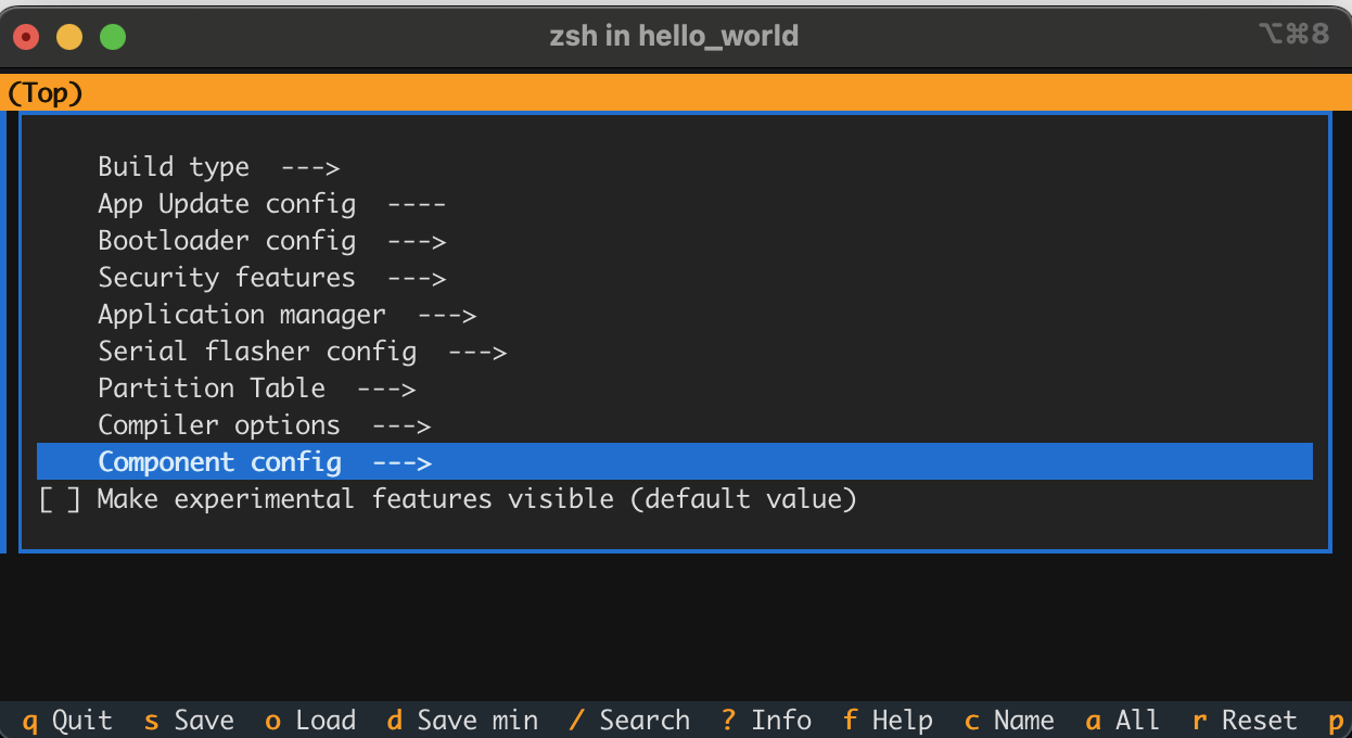
Now since hello_world doesn’t exactly need any WiFi credentials, SPI configuration, stack tweaking, etc. we don’t need to DO anything here; I’m just showing (like Espressif does) to imprint upon readers so they know it’s there when they need it. On to the bitslinging!

$ hello_world idf.py build
[525/530] Linking C static library esp-idf/main/libmain.a
[530/530] cd ~/sr...31/hello/hello_world/build/hello_world.bin
hello_world.bin binary size 0x1ee70 bytes. Smallest app partition is 0x100000 bytes. 0xe1190 bytes (88%) free.
[ ...  ] Project build complete. To flash, run:
idf.py flash
or
idf.py -p PORT flash
or
python -m esptool --chip esp32 -b 460800 --before default-reset --after hard-reset write-flash --flash-mode dio --flash-size 2MB --flash-freq 40m 0x1000 build/bootloader/bootloader.bin 0x8000 build/partition_table/partition-table.bin 0x10000 build/hello_world.bin
or from the "~/src/s31/hello/hello_world/build" directory
python -m esptool --chip esp32 -b 460800 --before default-reset --after hard-reset write-flash "@flash_args"
$ hello_world  idf.py --preview -p /dev/cu.usb* flash
Connecting...
A fatal error occurred: This chip is ESP32-S31, not ESP32. Wrong chip argument?

WTH?

$ hello_world  find . -name \*.obj | head -3 | xargs file
./build/CMakeFiles/hello_world.elf.dir/project_elf_src_esp32.c.obj: ELF 32-bit LSB relocatable, Tensilica Xtensa, version 1 (SYSV), not stripped
./build/bootloader/CMakeFiles/bootloader.elf.dir/project_elf_src_esp32.c.obj: ELF 32-bit LSB relocatable, Tensilica Xtensa, version 1 (SYSV), not stripped
./build/bootloader/esp-idf/bootloader_support/.../bootloader_support_esp_err_codes.c.obj: ELF 32-bit LSB relocatable, Tensilica Xtensa, version 1 (SYSV), with debug_info, not stripped

That certainly violates principle of least surprise. Let’s redo things we’ve already done.

$ hello_world  idf.py --preview set-target esp32-s31

Oho. If you don’t use –preview in the set-target, it will announce that it sets the target (and bugs you to include –preview) but it doesn’t actually set the target. Let’s rebuild.  Now when we run file on those same objects, we see:

./build/CMakeFiles/hello_world.elf.dir/project_elf_src_esp32s31.c.obj: ELF 32-bit LSB relocatable, UCB RISC-V, RVC, single-float ABI, version 1 (SYSV), not stripped

Let’s upload:

idf.py --preview -p /dev/cu.usb* flash

and we see the comfort that it’s now including ESP32-S31 action:

python -m esptool --chip esp32s31 -b 460800 --before default-reset --after hard-reset --no-stub write-flash --flash-mode dio --flash-size 2MB --flash-freq 80m 0x2000 build/bootloader/bootloader.bin 0x8000 build/partition_table/partition-table.bin 0x10000 build/hello_world.bin

So let’s peek at the serial line. Here’s one complete output cycle:

ESP-ROM:esp32s31-20251218
Build:Dec 18 2025
rst:0xc (SW_CPU_RESET),boot:0x78 (SPI_FAST_FLASH_BOOT)
Core0 Saved PC:0x2f004192
--- 0x2f004192: cpu_utility_ll_reset_cpu at ~/.espressif/master/esp-idf/components/hal/esp32s31/include/hal/cpu_utility_ll.h:24
--- (inlined by) esp_cpu_reset at ~/.espressif/master/esp-idf/components/esp_hw_support/cpu.c:49
Core1 Saved PC:0x2f0042da
--- 0x2f0042da: esp_cpu_wait_for_intr at ~/.espressif/master/esp-idf/components/esp_hw_support/cpu.c:57
SPI mode:DIO, clock div:1
load:0x2f0740c0,len:0x16a0
load:0x2f06a2b0,len:0xc34
--- 0x2f06a2b0: esp_bootloader_get_description at ~/.espressif/master/esp-idf/components/esp_bootloader_format/esp_bootloader_desc.c:40
load:0x2f06cfb0,len:0x337c
--- 0x2f06cfb0: is_xmc_chip_strict at ~/.espressif/master/esp-idf/components/bootloader_support/bootloader_flash/src/bootloader_flash.c:915
entry 0x2f06a2ba
--- 0x2f06a2ba: call_start_cpu0 at ~/.espressif/master/esp-idf/components/bootloader/subproject/main/bootloader_start.c:27
I (32) boot: ESP-IDF a602e67b 2nd stage bootloader
I (32) boot: compile time Jun 19 2026 02:48:21
I (32) boot: Multicore bootloader
I (34) boot: chip revision: v0.0
I (35) boot: efuse block revision: v0.0
I (39) boot.esp32s31: SPI Speed : 80MHz
I (43) boot.esp32s31: SPI Mode : DIO
I (46) boot.esp32s31: SPI Flash Size : 2MB
I (50) boot: Enabling RNG early entropy source...
I (55) boot: Partition Table:
I (57) boot: ## Label Usage Type ST Offset Length
I (64) boot: 0 nvs WiFi data 01 02 00009000 00006000
I (70) boot: 1 phy_init RF data 01 01 0000f000 00001000
I (77) boot: 2 factory factory app 00 00 00010000 00100000
I (84) boot: End of partition table
I (87) esp_image: segment 0: paddr=00010020 vaddr=40018020 size=075cch ( 30156) map
I (99) esp_image: segment 1: paddr=000175f4 vaddr=2f000000 size=00a24h ( 2596) load
I (102) esp_image: segment 2: paddr=00018020 vaddr=40000020 size=11b68h ( 72552) map
I (119) esp_image: segment 3: paddr=00029b90 vaddr=2f000a24 size=0a0fch ( 41212) load
I (127) esp_image: segment 4: paddr=00033c94 vaddr=2f00ab80 size=024d0h ( 9424) load
I (132) boot: Loaded app from partition at offset 0x10000
I (133) boot: Disabling RNG early entropy source...
I (145) cpu_start: Multicore app
I (154) cpu_start: GPIO 59 and 58 are used as console UART I/O pins
I (154) cpu_start: Pro cpu start user code
I (155) cpu_start: cpu freq: 320000000 Hz
I (156) app_init: Application information:
I (160) app_init: Project name: hello_world
I (164) app_init: App version: 1
I (168) app_init: Compile time: Jun 19 2026 02:48:21
I (173) app_init: ELF file SHA256: 9a6c37f27...
I (177) app_init: ESP-IDF: a602e67b
I (181) efuse_init: Min chip rev: v0.0
I (185) efuse_init: Max chip rev: v0.99
I (189) efuse_init: Chip rev: v0.0
I (193) heap_init: Initializing. RAM available for dynamic allocation:
I (199) heap_init: At 2F00E900 len 0006C6B0 (433 KiB): RAM
I (204) heap_init: At 2F07AFB0 len 000041C0 (16 KiB): RAM
I (210) heap_init: At 2E000000 len 00007FE8 (31 KiB): RTCRAM
I (215) spi_flash: detected chip: generic
I (218) spi_flash: flash io: dio
W (221) spi_flash: Detected size(16384k) larger than the size in the binary image header(2048k). Using the size in the binary image header.
I (234) sleep_gpio: Configure to isolate all GPIO pins in sleep state
I (240) sleep_gpio: Enable automatic switching of GPIO sleep configuration
I (247) main_task: Started on CPU0
I (247) main_task: Calling app_main()
Hello world!
This is esp32s31 chip with 2 CPU core(s), WiFi/BLE, 802.15.4 (Zigbee/Thread), silicon revision v0.0, 2MB external flash
Minimum free heap size: 478304 bytes
Restarting in 10 seconds...
Restarting in 9 seconds...
Restarting in 8 seconds...
Restarting in 7 seconds...
Restarting in 6 seconds...
Restarting in 5 seconds...
Restarting in 4 seconds...
Restarting in 3 seconds...
Restarting in 2 seconds...
Restarting in 1 seconds...
Restarting in 0 seconds...
Restarting now.

Perfect! We have taught our 300 MHz beast to count backward to ten…after printing hello world.

Next?

Hazards of Engineering Samples

This is a 300 MHz part. 🙁

60 GPIOs. Zero free

So I’m working on a project and successfully brought up the software on ESP32-S3 N8R16 (CYD), ESP32-P4 (Tab5), and Korvo. All I needed was to attach one teensy little little sensor.

and just like that, Korvo is out of the running…

Well, not just like that, I had engineering diligence to do. ESP32-S31 has 60 GPIOs; this should be easy. Let’s consult the official ESP32-S31 Korvo pinout.

Do you see all those unassigned pins? Yeah. Gulp. Twelve for the camera. Twenty-three (!) for the screen. (/me waves hand broadly) Five for audio. Six for SDIO. I won’t read the whole list. There are no available pins on this board if you want to use all the existing features.

I could, uuuuh.

  • Rob one from the sound, as my application doesn’t REALLY need sound. Stealing PA_CTRL would be kind of obvious.
  • Remove the camera connector and solder my pin to that connector or find a camera somewhere and cut up a ribbon connector.
  • Solder to the WS2812 at the bottom of the board. WS2812s are write-only, and my device was read-only.
  • Steal the boot button. It’s only read at boot. My code wouldn’t release the reset on the device that would start wiggling that pin until after boot, so that’s not totally crazy. Oh, they’re already overloading GPIO61 for the LCD’s SPI Clock.
  • I could use one of the buttons (Volume +/-, Set, Mode), right? Haha, Espressif already did this math. All four of those pins go to GPIO_42 with a unique resistor value in a resistor pulldown ladder into an ADC. Depending on if the value read is the difference of (I could do this math. I’m not going to) 10K and (13k, 6.8k, 3.3k, 1.3k) software can figure out which button is pressed. Software probably COULD figure out chords of multiple buttons, but I’m guessing most won’t.

There is *a glimmer of hope* I did actually find two pins—that I groused about earlier in this post—that are somewhat available and that are connected not only to pads that. a human could solder to, but that is brought out to a commodity connector. I could steal one of the USB pins that are USB_DP and USB_DM and rely on the internal GPIO pin mux to connect that to the peripheral I needed. Putting my sensor on a USB-A connector would give me power, ground, input, and the output that would be nice, but optional. It also seems pretty crazy…and still the least crazy of these options.

Epilogue: ESP32-S31 itself is a great chip and screams on my project. If you need exactly the peripherals that Korvo offers, it’s a nifty board to get your code up and running with screen, camera, and A/V-centric peripherals. If you need to add your own peripherals, you should probably instead be working with the Espressif ESP32-S31 Coreboard.
This doc will continue to grow…

This is just my notes from plugging it in and backing up the (awesome) factory demo. Next up: Hello World! (done)

Edit: Aug 22. Necessary changes

Edit: Neovim/LSP keybindings added

I’ve come to accept that I’m an old-school vi user. With about forty years of muscle memory behind that sentence, I’ll say that I’m an effective vi user, but in today’s world of C++ overrides, sentence-long symbols, and huge lists of available methods, I _have_ felt the occasional pang of jealosy and tried to move beyond bare bone vi. I’ll then sit back down at the terminal two days later, completely forget about that snazzy new editor that I told myself I’d learn, and immediately be back to a couple of iTerms with ack-grep just from habit. Making matters worse for myself, most of the time these days I work on ESP32 projects, so I’m dealing with cross compilers. Well, I’m not unhappy about that – having basically the same compiler on my embedded device as I do on my desktop is actually pretty sweet, but they’re always just different enough to be annoying. One difference that surfaces is that clangd-like services for Language Server Protocol (LSP) are usually just out of reach. One recent day when alternating between fighting CLion and vi (OK, it was probably actually vim; though I have flirtations with nvim.) I set out to win this battle.

It turns out there’s a slew of annoying behaviour you must overcome to get niceties to work. As is my style, I don’t declare this is the One True Way or even the Only Way. It’s just the journey that I took and I’m sharing it in the hopes that it saves you a few hours in your own journey. I’ll focus first on CLion and ESP32 because from there, “winning” with nvim is just an exercise in persistence. If it’s your goal to ignore CLion and focus on nvim or other clangd consumers, the steps to skip should be self-evident.

CLion claims to be able to use a platformio.ini. This is at best partially true. It can read the list of [env:] projects and give you a list of -e options that it will pass when shelling out to the (already slow and often broken) Platformio ‘pio’ command. By default, when given my (admittedly non-trivial, but hardly back-breaking) platformio.ini of 53 environments, we’re met with a red “Index 0 out of bounds for length 0”. No hint is given on what array was being indexed, what source file might be responsible, or even what language might have issued this error. All #included files are red squigglies because it can’t find them. No symbols have hover text unless they’re declared in the file you’re looking at, and syntax highlighting is about as effective as regex highlighting ever is on C++. Good job, Jetbrains.

Populate CLion’s shadow build system:

$ pio project init --ide clion

Resolving demo dependencies... (demo is the name of one environment in my platformio.ini that I'll use throughout)
Already up-to-date.
Updating metadata for the clion IDE...
Project has been successfully updated!

Restart CLion to see the changes.

$ open -a clion . (or whatever pointy clicky equivalent gives you joy)

It’s my experience, after probably a hundred restarts while developing this recipe, that this will fail on odd numbered invocations and pass on even numbered invocations… (Did I yet bitterly say “Good job, Jetbrains?”)

Now the bottom will show a blue progress bar during an ‘importing’ step that for me, takes about four minutes (!!) to complete. I have no idea why it takes long to analyze than it takes to completely build one or two of our targets, but I’m just a lowly bitslinger.

Restart CLion (twice) to see the changes.

Now it’ll still give the error and it still won’t convince you that it’s read platformio.ini, but it’s apparently necessary ritual sacrifice.

Build the Compilation “database”.

$ pio run -t compiledb -e demo

[ ... ]

Building in release mode
Building compilation database compile_commands.json

========================= [SUCCESS] Took 34.44 seconds =========================
Environment    Status    Duration
-------------  --------  ------------
demo           SUCCESS   00:00:34.439

========================= 1 succeeded in 00:00:34.439 =========================

Note that it will download and install all the packages required for all the builds (which is why I’m restricting it to ‘-e demo’ here or I’d be typing this until the cows came home. (Where do the cows GO anyway?) On my project, that’s about 20 libraries times 53 -e environments, so even though it’s not actually BUILDING much of anything, it’s still an exercise in persistence.

You now have a shiny new `compile_commands.json` file that describes what it would have invoked to build the software. Well, it doesn’t include the critical linking step, so it’s still not REALLY helpful if you’re trying to do what a ‘pio run’ would do, but it would tell you what the first 99% of a build will do. In my case, it’s 830 lines of blindingly dumb JSON that makes no attempt to factor out redundancy. These files ARE handy if you want to see what flags really really get applied to your build without looking at `-v`.

Purge the old CLion config

rm -fr .idea 

Now tell CLion to open that directory. It will recognize `compile_commands.json` and open it. The bottom of your tools menu will now have an option for Compilation Database. Your source tree will now show your source AND the zillion files in `~/.platformio/packages/framework-arduinoespressif32/libraries/*/src` that are ACTUALLY built. It also now knows where all your includes are as well as the system includes.

Notice that you can do OK living a bit of a lie here. The include paths for a lot of the system stuff actually change slightly depending if you’re targeting LX6 (ESP32-Classic), LX7 (ESP32-S2 or ESP32-S3) or RISC-V (everything else), but unless you’re working at the very bottom of the stack and NEED to know which source is used for the system stuff, it’s probably OK.  If it matters, you can repeat the pio run -t compiledb with a different -e and then reload the compilation database.

So this is great, right?

No. This is OK for editing in CLion, but you can’t actually BUILD in CLion this way. Despite giving it agonizing details of every invocation of g++, every one of the hundreds of `-I` flags and all that other stuff (look in `compile_commands.json`, seriously!) it won’t actually build code. You still have to open a window and `pio run -t upload -e foo` for that. There may be workarounds for that, but we’ll come back because vim is where work gets done while CLion is nice for fix-ups and clang warnings. Let’s forge on.

We have a great compile_commands.json, we can surely now rely on LSP support in nvim, right?

No.

We’re thwarted by many things. It seems that, despite having these agonizingly detailed roadmaps describing how to compile (almost) everything, both `clangd` and CLion have their own internal whitelists of toolchains. If your g++ binary isn’t whitelisted, it will silently fail and then try to invoke the native compiler. So the first time you hit, say `<vector>` or `<cstdio>` everything hits the fan because your MacOS or native Linux `/bin/g++`’s headers are in the “wrong” place and they call things that aren’t in the `-I` paths that are given. For MacOS, `_ansi.h` seems to be the poison pill, but if it weren’t that file, it would be something else.

I’ll skip ahead about two hours of debugging, but the solution lies in creating a .clangd in the root of your project’s directory to add the flags that you need and to strip the flags that nvim tries to add to the build that would choke your cross compiler, like anything starting with -m because you’re presumably compiling for a different machine architecture.

CompileFlags:
  Remove:
    - -m*
    - -fno-tree-switch-conversion
    - -fstrict-volatile-bitfields
    - -Wno-frame-address

  Add:
    - -nostdlibinc
    - -nostdinc++

I’ll fast-forward you through another two hours, though, and tell you that the `clangd` on Mac is so hell-bent on developing for Mac that it will ignore the above and STILL add things to its own include path that are toxic to the cross compiler. This is because Apple’s `/usr/bin/clangd` is a stripped-down, lobotomized version tied to Xcode that lacks standard features and stubbornly injects Apple-specific flags. The solution to this is to install `clangd` from Homebrew (`brew install llvm`) and then add a wrapper file (remember to mark it executable) in a directory in your `$PATH` that’s before the system binary. I already had `~/.local/bin/` in my PATH, so I’ll just add that.

My new ~/.local/bin/clangd:

#!/bin/sh

# Find the real clangd by listing ALL instances and skipping this wrapper
#REAL_CLANGD=$(which -a clangd | grep -v "\.local/bin/clangd" | head -n 1)

REAL_CLANGD=/opt/homebrew/opt/llvm/bin/clangd

# Execute it with the query-driver argument pointing to the global PlatformIO directory
exec "$REAL_CLANGD" --query-driver="$HOME/.platformio/packages/**/bin/*g++*,$HOME/.platformio/packages/**/bin/*gcc*" "$@"


Testing this mess without the editor

You’ll know this is in the game when you can do something like:

$ clangd --background-index --check=src/main.cpp 2>&1 | less

(Lipe-pro-tip: `–background-index` is generally a good flag to add in your editor setups so `clangd` can eagerly cache your project and make cross-file navigation instant.)

and see the  presence of:

I[01:22:30.648] Loading compilation database...
I[01:22:30.667] Loaded compilation database from ...
I[01:22:30.668] Compile command from CDB is:...

…and output that ends like:

I[01:23:24.137] All checks completed, 6 errors

It’s not important that it be zero. It’s important that it not be so many that clangd aborts. In fact, it’s even normal to have hundreds of lines like

E[01:23:24.130] IncludeCleaner: Failed to get an entry for resolved path : No such file or directory

or

E[01:25:02.807]     tweak: ExpandDeducedType ==> FAIL: Could not deduce type for 'auto' type

Despite these starting with “E:” and LOOKING like errors, this is expected.

** Note: if you tinker much with .clangd, it seems that a rm -fr .cache/clangd is sometimes needed. Since it’s not clear WHEN it’s needed and it tends to be pretty fast to just rebuild, if you’re working on this, just keep a rm -fr .clangd/cache ; nvim .clangd in your recall buffer.

NOW, you’ve slain the final boss between you and glorious nvim assisted by clangd via LSP.

<screenshot goes here>

Now, tab completion, hover, and auto clang-tidy all work sensibly. Victory!

But nvim screws up copy-paste?!?! Yeah, well…future battles to fight. *(Though if you want to skip the wrapper script entirely in Neovim, you can actually pass `–query-driver` directly in your `nvim-lspconfig` setup for `clangd` using the `cmd` table!)*

But I want to BUILD in CLion!

Since we bypassed CLion’s native PlatformIO integration (because it was choking on our 53 environments) and loaded the project as a bare Compilation Database, CLion doesn’t actually know *how* to compile your code. It just knows how to parse it. If you hit the hammer icon, nothing good happens.

To fix this, we need to teach CLion how to shell out to `pio`. We do this using Custom Build Targets.

1. Go to **Preferences / Settings -> Build, Execution, Deployment -> Custom Build Targets**.
2. Click the `+` to add a new target and call it something creative like “PIO Build”.
3. Next to the “Build” field, click the `…` to add an External Tool. 
4. Click `+` to add a new External Tool.

   – **Name**: `pio run demo`
   – **Program**: `pio` (or the full path like `~/.platformio/penv/bin/pio` if CLion’s `$PATH` is lacking)
   – **Arguments**: `run -e demo` (or whatever environment you want to actually build)
   – **Working directory**: `$ProjectFileDir$`

5. (Optional but helpful) Do the exact same thing for the “Clean” tool, passing `run -t clean -e demo` as the arguments
6. Save your new target.

Now, go to the Run/Debug Configurations dropdown in the toolbar (or **Run -> Edit Configurations**).

1. Click `+` and select **Custom Build Application**.
2. Set the **Target** to the “PIO Build” target you just created.
3. You can leave the Executable blank if you just want to build, or point it to your compiled `.elf` file if you have ambitions of setting up an Embedded GDB Server later.

Now you can smash that hammer icon or hit `Cmd+F9` (or your OS equivalent), and CLion will obediently shell out to PlatformIO, build your project, and dump the output in the console window.  If the native Platformio support worked, that’s all it would do for you anyway.

You’ve finally got the best of both worlds: CLion’s shiny graphical UI, proper code insight and navigation powered by your compilation database, and the actual build process correctly handled by PlatformIO. And when you’re ready to get real work done, your `.clangd` and wrapper script mean Neovim is sitting right there in your terminal, ready to go with full LSP support.

Take a victory lap. (And/or a beverage of your choosing.) You’ve earned it.


Shifting sands. Article changes.

I admittedly don’t use this configuration every day. I’d noticed that it had quit working, but I also wasn’t certain that I’d tested it on this exact configuration so I let it coast until that little rock in my shoe annoyed me enough to tackle it. Still, I knew my approach was sound but I couldn’t suss it out. Eventually, I asked my friend Gemini (Antigravity) to help. I’m leaving the above unedited because that probably works for some configurations. Here’s what we discovered.

  • On this system, my $HOME is a symlink to an external SSD. (Thank you, Apple for your extortionistic storage prices.) My ~/.local/bin/clangd suffered from a one-two punch of overly strict matching and an update to PlatformIO moving the internal platform file.• What changed: We pointed REAL_CLANGD away from Homebrew’s LLVM and directly to the esp-clangd binary installed by EIM (~/.espressif/tools/esp-clangd/…).
    The sneaky fix: EIM actually splits esp-clangd and esp-clang into two completely separate directories. This means the clangd binary doesn’t know where its own built-in headers are! We had to append –resource-dir=”~/.espressif/tools/esp-clang/…/lib/clang/21″ so it
    could find basic things like stddef.h. While we are here, we tweaked things so we only apply all this cleverness if we have a .platformio.ini containing the word “espressif” (so nvim on native projects still work) AND we dig around in the espressif tree to find the most recent esp-clangd.

    Updated file:

    $ cat ~/.local/bin/clangd
    
    
    #!/bin/sh
    
    # 1. Detect if we are inside an ESP32 PlatformIO project
    
    if [ -f "platformio.ini" ] && grep -qi "espressif" "platformio.ini"; then
    
        # 2. Dynamically find the newest esp-clangd and resource dirs
        ESP_CLANGD_DIR=$(ls -rd "$HOME"/.espressif/tools/esp-clangd/* 2>/dev/null | head -n 1)
    
        REAL_CLANGD="$ESP_CLANGD_DIR/esp-clangd/bin/clangd"
        ESP_CLANG_DIR=$(ls -rd "$HOME"/.espressif/tools/esp-clang/* 2>/dev/null | head -n 1)
        RESOURCE_DIR=$(ls -rd "$ESP_CLANG_DIR"/esp-clang/lib/clang/* 2>/dev/null | head -n 1)
    
        # 3. If the ESP tools exist, use them
        if [ -x "$REAL_CLANGD" ] && [ -d "$RESOURCE_DIR" ]; then
    
    exec "$REAL_CLANGD" \
    
         --query-driver="$HOME/.platformio/packages/**/bin/*g++*" \
         --resource-dir="$RESOURCE_DIR" \
         "$@"
        fi
        # If the ESP tools were missing, it safely falls through to the system default below
    fi
    
    # 4. We are NOT in an ESP project (or ESP tools are missing).
    # Fall back to standard desktop C++ clangd.
    # Find the first clangd that IS NOT this wrapper script itself.
    SYSTEM_CLANGD=$(which -a clangd | grep -v "\.local/bin/clangd" | head -n 1)
    
    if [ -n "$SYSTEM_CLANGD" ]; then
        exec "$SYSTEM_CLANGD" "$@"
    else
        echo "No system clangd found." >&2
        exit 1
    fi
    
    if [ -n "$SYSTEM_CLANGD" ]; then
        exec "$SYSTEM_CLANGD" "$@"
    else
        echo "No system clangd found." >&2
        exit 1
    fi
  • NeoVIM (AstroNVIM?) changed direction, requiring tweaks to the Neovim Config (~/.config/nvim/lua/plugins/astrolsp.lua)
    • What changed: We explicitly set cmd = { “/Users/robertlipe/.local/bin/clangd”, … } instead of just “clangd”.
    • Why it broke your previous setup: AstroNvim recently integrated Mason very tightly. If you just ask for “clangd”, Mason intercepts your $PATH and silently launches its own vanilla LLVM clangd. This completely bypassed your wrapper script, dropping your –query-driver argument, and putting you back to square one. Hardcoding the absolute path forces Neovim to respect your wrapper. Solution:Add a section under “servers…pyright” stanza

        servers = {
          -- "pyright"
        },
    
        -- customize language server configuration options passed to `lspconfig`
        ---@diagnostic disable: missing-fields
        config = {
          clangd = {
            cmd = {
              "/Users/robertlipe/.local/bin/clangd",
              "--background-index",
            },
            capabilities = { offsetEncoding = "utf-8" },
          },
        },
    
        -- customize how language servers are attached
        handlers = {
          -- a function without a key is simply the default handler, functions take two parameters, the server name and the configured options table for that server
    
  • I moved to C++26 and this made PlatformIO grumpy – Changes to .clangd required
    A few months ago, I bumped my minimum platform requirements to C++26 (because I can). PlatformIO adds its own –std= lines into the build and depending on the time of day, that can come before or after my own entry. GCC parses arguments left to right, so the last one standing ‘wins’. When calling clang-format, it was getting reset, so my
    static_assert(__cplusplus > 202002L, "This project requires C++26");
    was sending the parse down in flames.
    • What changed: We keep the Remove: block to strip out the GCC-specific optimization flags that cause warnings. However, we were able to delete -nostdlibinc and -nostdinc++. We have to add back the -std=gnu++2b flag.
    • Why it’s better: Because you’re now using Espressif’s custom clangd, it natively understands the Xtensa target. You no longer have to manually nuke the Apple standard headers because Espressif’s parser doesn’t confusingly fall back to macOS Mach-O headers anymore!You officially have the ultimate setup. No cosmetic #error in limits.h, native understanding of .iram1 ELF sections, and perfect C++ standard library resolution!


Appendix: Neovim/LSP Keybindings (the reason we do this…) 

Since this is largely documentation for myself, here, at no extra cost to you, is a subset of the keybindings that are most useful.

Feature Keybinding Lua Function/Command What it does
Hover Documentation K vim.lsp.buf.hover() Pops up a floating window showing the comment block, type info, and documentation for the symbol under your cursor.
Go to Definition gd vim.lsp.buf.definition() Jumps straight to where the variable, function, or class is defined.
Go to Declaration gD vim.lsp.buf.declaration() Jumps to the header declaration (very handy for C++ header/source splits).
Document Symbols gO vim.lsp.buf.document_symbol() Lists all methods, classes, and variables in the current file so you can fuzzy-search through them.Code Actions
Code Actions gra vim.lsp.buf.code_action() Fixes missing includes, implements virtual methods, or applies automated refactors.
Smart Rename grn vim.lsp.buf.rename() Renames a symbol safely across your entire project workspace.
Type Definition grt vim.lsp.buf.type_definition() Jumps to the underlying type definition of a variable.
Go to Implementation gri vim.lsp.buf.implementation() Jumps to subclasses or concrete implementations of a virtual interface.
Find References grr vim.lsp.buf.references() Scans your entire project and lists every place that symbol is used.


There is a more comprehensive version of Neovim LSP Keybindings

Beagle-V welcomes you to 2012.

I wanted to like the new Beagle-V. It was the developer edition of Beagle-V (that was canceled) that was my introduction to “big” RV64G systems and I loved working on that board. It was canceled abruptly during development and Beagle wandered around in the weeds for a few years, but they finally announced a new RISC-V Beagle-V that they intend to actually ship.

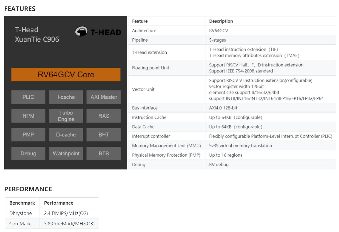
Since it’s basically another TH-1520 reference design, there’s not a huge amount to say about it, so I’d planned to say nothing. (I just can’t get excited about the Th-1520 and other C906/C910 derivatives.)

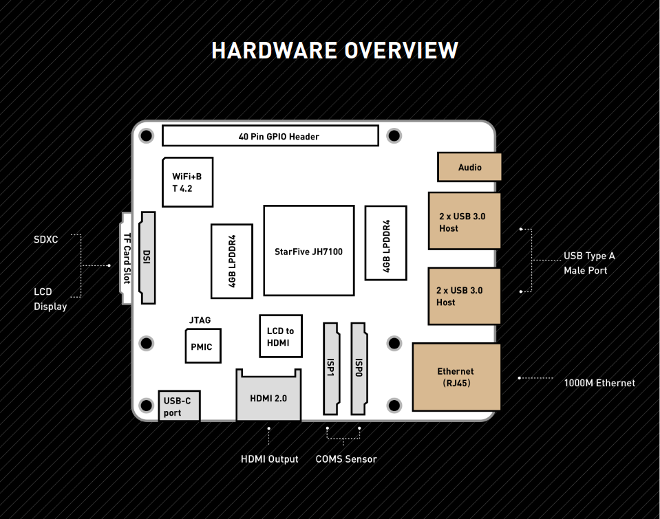
Then I looked closely at their picture.

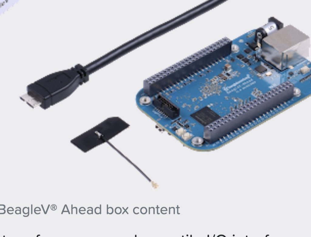
USB 3.1 Gen 1 Cable sighting ... in 2023

They’re actually using a USB 3.1 Gen 1 Micro-B SuperSpeed Cable (… “Pro Plus Dominator 2000 ‘on a steeeck'” edition)  in 2023 almost ten years after USB-C became mainstream.

I can think of only three explanations.

1) Someone in purchasing found a “deal” on thousands of these much hated  and largely forgotten about cables.
2) Someone has an surplus inventory of cables from that hated connector to USB-C so it can actually connect to your machine and is hoping to liquidate them.
3) Common drug use in the workplace.

This connector was hated and almost immediately retired because it was the worst of all worlds. It had the flimsiness of Micro-B (the break-away design was actually a feature, not a bug – it was meant to sacrifice the cable instead of your $1000 phone if pulled on at an angle). It could be used with either a normal Micro B (with all the problems that connector had, including random power capabilities) or Micro B super speed, which was a very expensive and bulky connector, ensuring you couldn’t plug anything next to it. You never REALLY knew if all the pairs in the cable worked, so you’d get a speed that was either Super or not. Seagate used them on a generation or two of MyBook class drives and some laptop monitors used them because they needed the USB 3.1 bandwidth and USB-C hadn’t arrived yet in volume. There’s no mechanical latching, so you never know if it’s fully seated. As they were only popular for a few months, the odds of having spares are rare. The SuperSpeed branding was so weak you never really knew if that was a 5 or 10Gbps connection, though they’d sometimes degrade to 6 or 8 Gbps if a pair was sensed to fail.

I wouldn’t be surprised if these cables and accessories are out of manufacture. It’s not like you’re going to get a new pod for your protocol analyzer or extension cord or other nicities.

That connector is the USB equivalent of the CCS connector for charging EVs: they had another connector that they wanted to be compatible with, but they needed extra pins/wires, so they added a sidecar connector onto the connector.

CCS connector
CCS Connector. Human hand for scale.

Some will say it’s a bit silly to get worked up about the cable when you will power it from the barrel jack (which might be 5521 or 5525, each slightly incompatible, and in a variety of voltages or current instead of the perfectly lovely USB-C Power Delivery, which would get your computer AND power connection in a single cable.) or will never rely on a computer connection at all because WiFi and copper ethernet are provided, but details matter.

If this were an Amazon review, incompatibility with common, standard, relevant connectors is an immediate two stars off in my Amazon reviews.

Still, Beagleboard is a reputable company known for community-building. Lots of people prefer working with them over the companies that just lay down schematics on fiberglass and throw it over a wall as is done by many competitors that compete primarily on price. Certainly, the few months I spent working on the original Beagle-V were very pleasant for exactly that reason.  I wish them luck with this board.

…but don’t do it again, team, mmmkay?

Many of us have been pretty disappointed in the long lead time it takes to get chips from specification into production.  For RISC-V devotees, this was brought into clearest focus this year where November of 2021 brought us ratified specification for Vector Computing 1.0, in particular, but we’ve mostly developed via emulated cores in software or FPGAs  or through chips like Allwinner’s D1 family of parts which paired a single core with a pre-release version of the Vector spec that was already over a year old when the device shipped. Lucky for us, we may see history repeating in the one year part of that with first Vector 1.0 silicon coming late this calendar year, so likely November or December.

Many of us had hopes that StarFive, with their close ties to IP vendor SiFive, and their collective “dry-run” experience with shipping many hundreds of chips through BeagleV, Starlight, VisionFive which in the upcoming JH-7110 iteration DOES bring around 3D graphics, and four 1.5Ghz cores along with a comfortable (2-8GB) headroom of RAM. The Kickstarter from StarFive was successful with over 2,000 units and that’s easily one of the most anxiously awaited parts of 2022, with Pine64’s fast-following board adding PCIe graphics/other expansion slot,

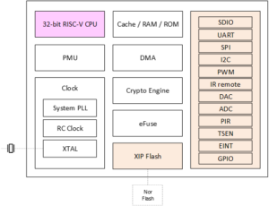
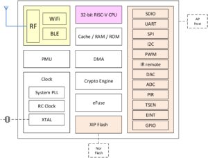
The new part has generated less buzz, because while it has been known for a few months, it was under press embargo until now,  It comes from Shenzhen’s Bouffalo Lab which is relatively unknown outside of RISC-V developer circles. They’re very much a Chinese company and their Western presence can be pretty tricky to find a pulse for, but they have a family of developer tools with (mostly) enough English documentation, tools, and support. While they have really inexpensive I/O chips, their chips will be mostly known by readers of this page as being the brains of Pine64’s Pinecone and reduced pin count Pine Nut. In broad strokes, those BL602 and BL604 chips are comparable to the ESP32-C3, with a SiFive E24 core and a basket of I/O, including Bluetooth and WiFi. Cousins BL702 and 706 add more GPIO, may trade WiFi for Zigbee in certain models, and have cost/performance models that make it possible to emulate an FTDI in software, suitable for a $3.59 JTAG board ir drive full size panel displays while feeding WiFi services, GPIO monitoring, and such. They’re very flexible parts.

The zinger here is that for BL808, their newest chip (expected “soon”) we leave behind the SiFive cores and go with the cores that were open sourced by Alibaba’s chip division, T-Head about last year. Bouffalo was able to pair T-Head’s experience in high-speed cores with their own experience in fabbing high-volume/high-volume parts, and fuse in value like the new Vector 1.0 specifiction. Now that we have ~18 months or more of experience in simulating and building software for those parts via LLVM and, less so, GCC, that seems like a great partnership.

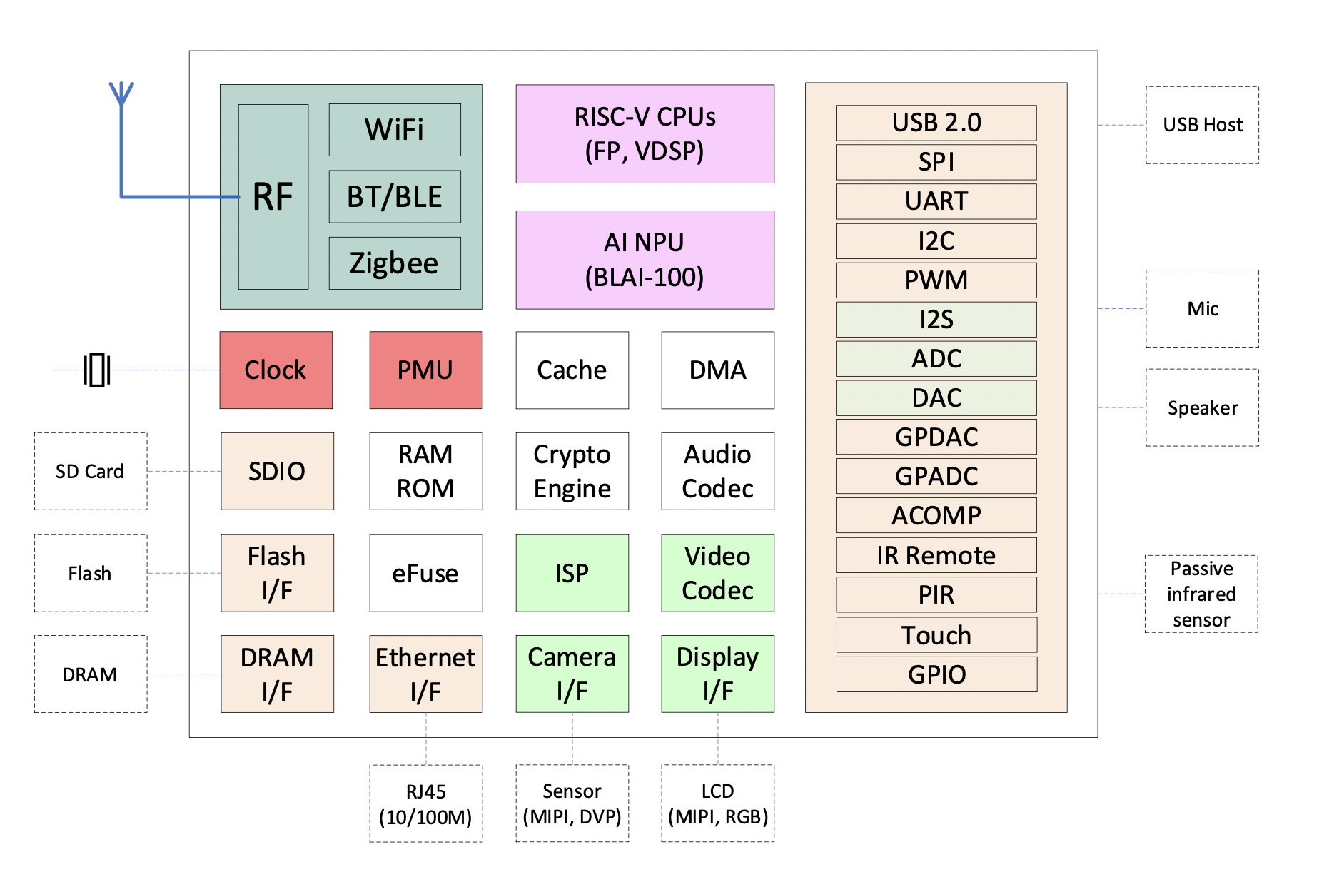
The coarse-level datasheet is almost self-deprecating. “Take four marginally related compute nodes and attach everything to everything” look:

Bouffalo did what they did best, and Sipeed is on deck to do for this chip what they did to the (then) ground-breaking GD32VF103 (zillions of <$10 RISC-V boards without cables and a very usable SDK) or the K210 – which they morphed into a dozen form factors and married an early Rocket design with a numeric computation unit made FL acceleration/AI  accessible to the < $20USD developer in many packages. So what makes BL808 a good date to bring to the computing ball of 202x? 

Integration. The likes of Sipeed, Pine64, and others will mount the board to a variety of backing form factors so people wanting access to these can just use them without having to wire-wrap them or hire a high speed digital logic team to take all the high speed timing craziness.

Tool stability. RISC-V is probably the first real ocean of silicon tech that’s had the software team delivering on high before the hardware team could make wafers. RISC-V is simulated, the tools are validated, and these tools are all available at the risk/scale/price point you want to pick.

ZZZZZZ TODO: Insert 3-wide frame of chip cut-ways and QR’s here.

There are already hundreds of pages of documentation available online. It’s probably not the best place, but it’s the first place I’ve seen that’s publicized in a way that doesn’t look like like a leak. :–)

Of course, the chips themselves have RealTimeCounters, 20-channel Direct Memory Access Controllers (as we do) , USB2,  JTAG, SPI, four UARTs and all those other creature comforts that we essentially expect to see in our $10 chips these days. (Pricing hasn’t been announced…)  This part has so many processing/IO cores that it’s actually hard to distinguish them.

“The wireless subsystem includes a RISC-V 32-bit high-performance CPU, integrated Wi-Fi /BT/Zigbee wireless…”
“The multimedia subsystem includes a RISC-V 64-bit ultra-high-performance CPU and integrates video processing modules such as DVP/CSI/ H264/NPU, which can be widely used in various AI fields such as video surveillance/smart speakers….”
“NPU (numeric processing unit) HW NN (hardware neural networking) co-processor (BLAI-100 – Bouffalo Logic Artificial Intellligence) generally used for AI applications
Of course, there’s also a low-power 32-bit RISC-V unit to babyset THOSE four compute modules, because it’s 2020 and why the hell not!!!

You literally end up with M0 having “32-bit RISC-V CPU with a 5-stage pipeline structure, supports RISC-V 32/16-bit mixed instruction set, contains 64 external interrupt sources, and 4 bits can be used to configure interrupt priority.”
D0 has “a 64-bit RISC-V CPU with a 5-stage pipeline structure, supports the RISC-V RV64IMAFCV instruction architec- ture, contains 67 external interrupt sources, and 3 bits can be used to configure the interrupt priority.”

As a software engineer, your job as a shepherd is to keep all the computing power your customers have being asked to pay for busy, but not overloaded. Don’t awaken a 64-bit core with an FPU fi you can service your immediate need (maybe it’s a temperature sensore recognizing something is hell-bound)  can be handled by a mostly 16-bit, integer-only RISC-V part. Of course, lighting up the numeric inference cores brings on a very different source of power and performance tradeoffs.

Of course, the chip has the mandatory boat of timers, PWMs, ethernet (10-100Mbps only)  and more. It really is quite ridiculous what a couple of dollars and 88 pins will buy in modern time. It’s an added bonus that these parts are expected to be available with less than a 104-week lead time. 🙂

These look like very cool chips and I look forward to seeing board from the likes o Sipeed, and maybe Pine64 or BeagleV very soon. I haven’t seem formal pricing yet, but I expect to see full boards for less than comparable D1 boards, but to have the added benefits of standard compliance (ahem, those page table bits and jumping the gun on V without pushing it into the reserved opcode space…) over the Allwinner parts. These should be priced way under the JH-7110’s, but have the edge of NPU’s (particularly when pairdd with Sipeed’s new MaixWHATISTHATCALLED?LOOKITUPROBERT) library that makes NPU/Tensor-style programming pretty easy..

Programmers, what tools do you need to see to takme these boards?
Hardware types, what playgrounds can you build for the programmers to fill?

Eventually: cc to lupyuen, caesar, bouffalo team, others for comments…

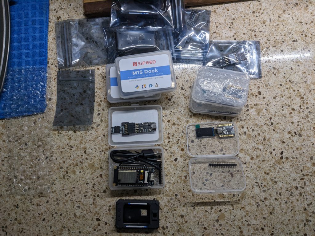
The much anticipated products from Sipeed, The M1S Dock and M0 Sense are now being delivered to customers. Mine arrived in the U.S on December 20, to my surprise as the tracking number never fired on USPS Informed Delivery and Fedex did not announce the delivery. These were purchased boards and are not prerelease.

M1S Dock

M1S Dock is a board with the Bouffalo BL808 Processor. It features three RISC-V cores: one 480Mhz 64-bit -T-head D906 variant that’s similar to the one in Allwinner’s D1 (including the outdated 0.7.1 vector unit, alas), one 320Mhz T-Head 32-bit E907 for coprocessing, and one low-power 150 Mhz T-Head RV32EMC core for super low power use, such as keyword recognition to awaken the others on demand. As a bonus, it contains NPU BLAI-100 (Bouffalo Lab AI engine) for video/audio detection/recognition.

The M1S Dock starts at $10.80 for the board with headers and ranges to $24 with camera, LCD, and case.

The device supports:

  • 2.4 GHz 802.11 b/g/n Wi-Fi  4
  • Bluetooth 5.x dual mode (classic + BLE)
  • IEEE 802.15.4 for Zigbee
  • 10/100M Ethernet through add-on board

There is 64MB of RAM and a “real” MMU with RV32, so while you’re not going to run your favorite Fedora workstation-class configuration on it, a ‘normal’ embedded Linux kernel and supporting utilities is quite practical.

Optional peripherals from Sipeed, pictured below, include the display, a debug board (which features yet another RISC-V part, the BL706, to bit-bang the debug protocol (which appears to NOT be JTAG), a camera, and a hard plastic case.

Image of M1SDock and M0Sense
M1SDock and M0Sense

Assembling the case is best described as painful. While it looks like a flexible silicone case, it’s not. It’s a hard plastic with a rubbery texture. The screen has to be removed from the double-stick tape holding it to the board, have the screen passed through the hole, have the screen fastened to the board, and then the board threaded into the case. Since the double-sided tape for the screen has a small area, I’m not expecting to be able to remove and re-insert the screen very many times.  If I’d known what a pain it was, I wouild have certainly soldered down the provided .100 posts before mounting it.

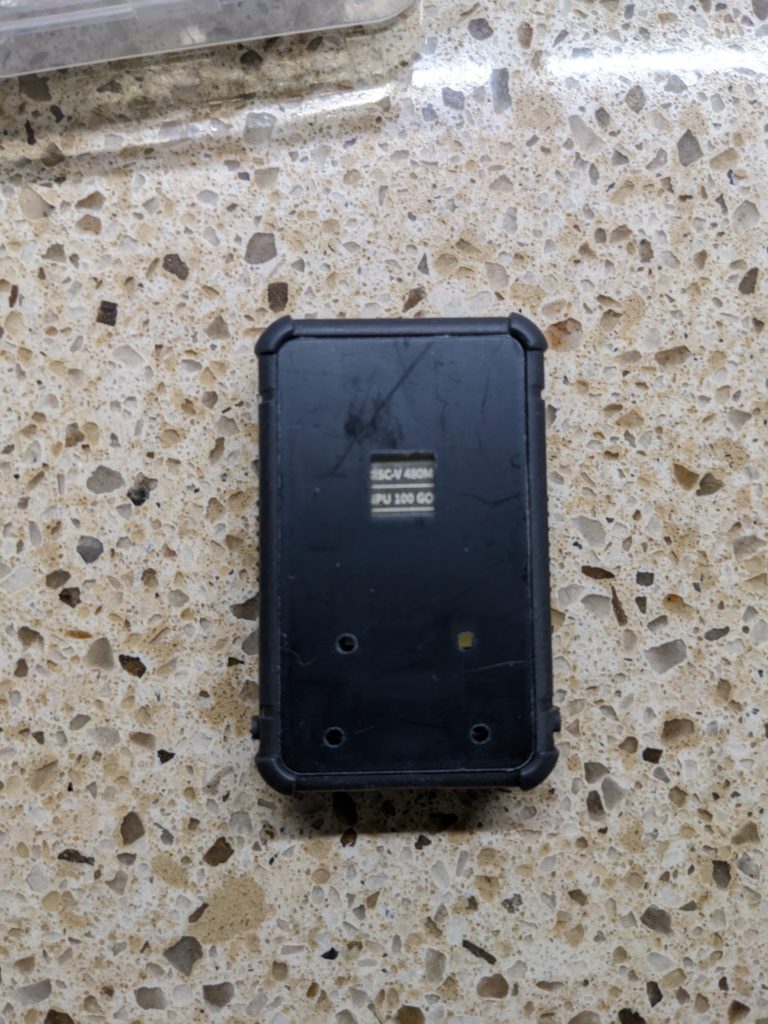
Image of Back of M1s Dock
Back of M1s Dock
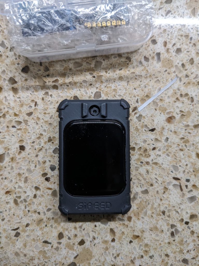
Image of Front of assembled Sipeed M1s Dock
Front of assembled Sipeed M1s Dock


Sipeed has done well providing documentation for the M1S Dock, including pinouts, a full SDK (with Bouffalo Labs) , AI Model and Framework, and a handy drag & drop approach to burning firmware. and many M1S Dock demos.

M0 Sense

Also delivered are the M0Sense boards. These are a lovable little alternative to nRF52480-class hardware. The featured processor is the BL702 at 144Mhz. Twelve of the sixteen pins are available I/Os and the board comes with Bluetooth, including BLE. The SiFive core is attached to 132K of ram and 512K of flash. The board provides an IMU and a USB Full-speed (12Mbps) interface. Computationally they may not take the dual-cores (and PIO) of the RP2040 products, but these are great alternatives in the RISC-V world that offer easy programming and plenty of powerful I/O.

The board starts at $4.50 USD. Adding the .96 screen makes it $5.99.
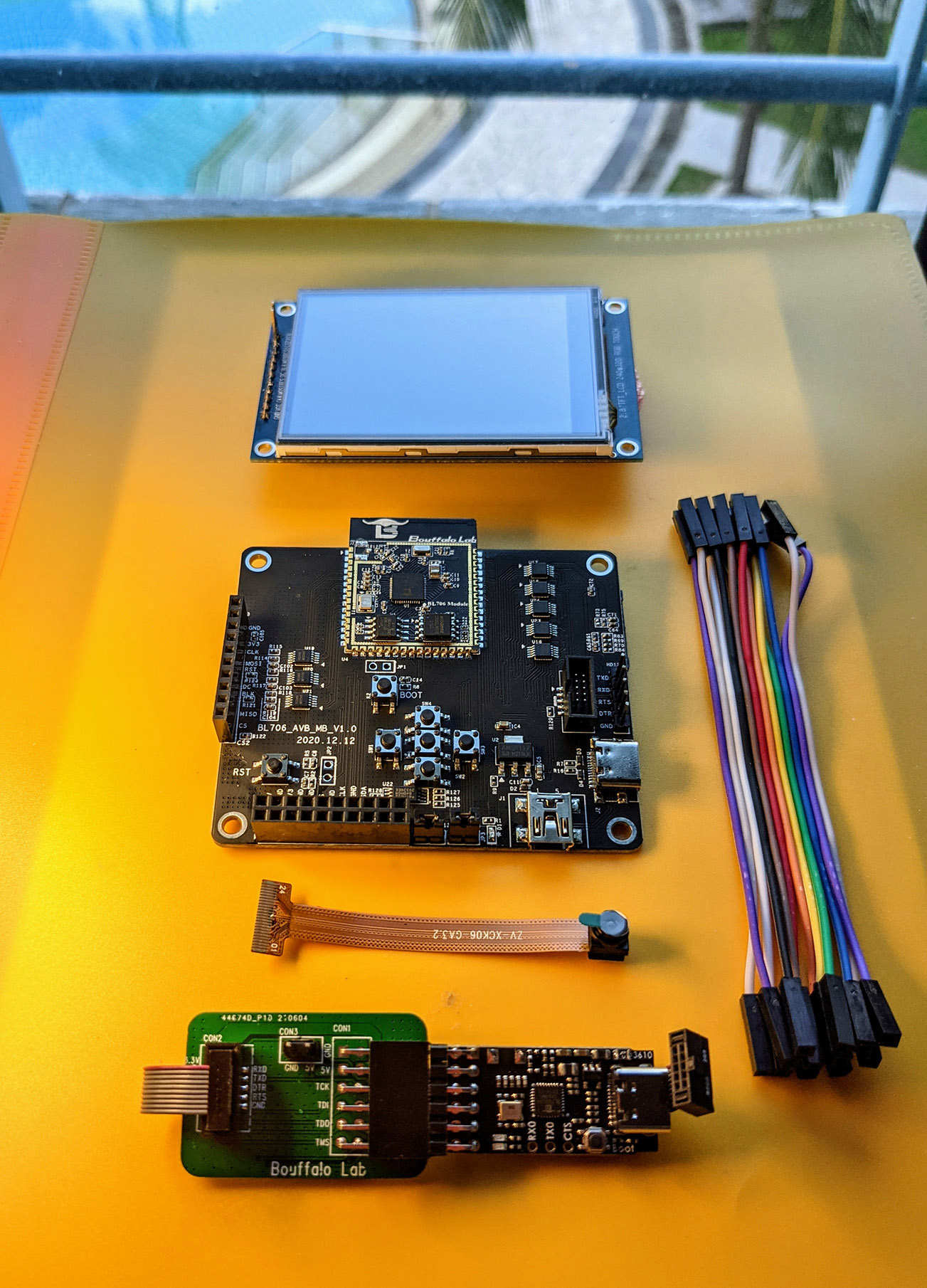
Sipeed has done well providing documentation for the M0Sense, including pinouts, a full SDK (with Bouffalo Labs) , AI Model and Framework, and a handy drag & drop approach to burning firmware. and many M0 Sense demos.

Summary

Between these boards, you have a very low-end sensor board with ML abilities for $4 that includes I2C, SPI, and all the normal things to connect to your own sensors AND a relatively high-end MCU with a dedicated ML coprocessor. With M1S Dock being a cousin to Pine64’s OX64, we’re sure to see a ton of software development around them. They’ve taken the sharp edges of Bouffalo’s unpleasant boot loader by providing a drag-and-drop capable boot loader. The BL808’s available RAM, performance, and price really makes it difficult to lean into the Kendryte K210 class of boards as we enter 2023.

I really look forward to exploring these boards in coming weeks and months. What do you plan to do with them?

Issues with USB-C powered development boards

Below – Hall of Shame:

The symptom: dead boards

More than once in my development time, I’ve been an early receiver of a development board that powers via USB-C. Invariably, the board is so new that there is no documentation provided with the board and little to nothing already existing on the web about it – after all, helping create some of that documentation is probably why I have the board. There may be no source code, no schematics, and no doc. I’m even pretty liberal in accepting early development documentation in Chinese – Google Translate is pretty amazing on technical material and Google Lens can help crack the case of all-too-common case of Chinese text baked of  images. (This is bad for accessibility, such as screen readers or even visual assists that may beed to expand text and be able to do a reflow…but that’s a different rant.)

For first power-up, there’s not really an expectation of any code being flashed into whatever kind of flash memory is available.  With SMT LEDs bragging about being .8 or even .65mm, it’s far from given that I’ll recognize an LED on the board at all just by visual inspection and even at that scale, silk-screens don’t much work, so the parts aren’t likely labeled. Similarly, there are often not recognizable chips on the boards that set expectations of how it should act if successfully connected. Sure, if there’s an FTDI 232H or a CH340, we can know to look for a USB serial device enumerating on the host PCI bus. However, microcontrollers like the ESP32-C3 or BL706 integrate USB right on the chip and may or may not implement USB CDC protocol, While that’s awesome for development (hooray, it’s a disk drive and I can just copy firmware to it!) it means you can’t depend on the visual cue of a Finder window popping open when the board is recognized.

This is a lot of words to provide background to the lede I’ve already buried in the title. The short version is that it’s not totally unexpected to connect a board and have exactly no visual confirmation the board is running and no recognizable signs of life from the computer.

In addition to all the above possible causes (no LEDs, no code flashed, required external boot knocking sequence required, no boot device present, device permanently in reset because it’s a jumper not a button (yes, really) there’s another that’s far more frustrating: the board developer did not read and understand the USB-C specification.

The cause: a poor understanding of USB-C

USB-C is more than USB 3.1 in a flippy connector, though that is undeniably nifty. It fundamentally changes how power is transferred over the wire because it allows bidirectional charging as well as bidirectional signaling (formerly “USB On The Go”) but because there’s way power potentially involved, particularly because it’s the first time more than 5v may be present on the power rails.  Failure to handle USB-C’s power requirements correctly can result in 24VDC being sent to your 25 year old floppy drive that was built into a 5V-only world and that’s bad.

For older USB, you could always count on at least 100mA of 5V on the power rails. As a practical matter, you could count on 500mA from most devices even without explicitly enumerating on the bus or even 900mA starting with USB 3.0. For lots of tiny development boards, that’s all plentiful.

On USB-C, there are two new pins on the bus named CC1 and CC2. If you have a device that may either provide or receive power (your laptop or your phone can charge your earbuds, but they can be charged over the same plug) then you need a Real USB controller chip  like an STM32 or a MAX77958 on the bus and you need a real EE that can read and understand the relevant specs in order to implement your Dual Role Port as that’s a more complicated case than a Sink Port (a load) or a Source Port.

A compliant USB-C Power Delivery Source Port (e.g. a high-quality USB-C charger or a laptop with actual USB-C jacks)  will monitor the CC1 and CC2 pins for voltages, nominally provided by a pair of resistors forming a voltage divider. The presence of a pair of 5.1k resistors (at a cost of a fraction of a penny in quantity to tie each of CC1 and CC2 to ground ) tells the power supply to deliver 5V at 3A.

If your device has a USB-C jack and does NOT provide those two resistors, the USB Power Source is under no obligation to provide power to your device. Your device will be unpowered and, most likely, will not work.

The full USB-C and related specs run into thousands of pages and this is probably just caused by misunderstanding that USB-C is just like its predecessors. Fortunately, there are good descriptions like this primer from ST on implementing USB-C power

“But it works on my PC”

If you have a USB-A to USB-C cable, it is known there can be no bidirectional charging so the resistors are present in the cable.

“Can I save an eighth of a cent and use one 5.1K resistor instead of two?”

No. Raspberry Pi foundation learned this very publicly and frustrated thousands of customers in the Raspberry Pi 4 defective USB implementation.

“But it almost works if I do it…”

It works except when it dosn’t. It may fail on e-marked cables (very common amongst uses of high-quality, high-power gear) but actual experts can explain why you need two individual 5.1k resistors on USB-C devices. Googler Benson Leung made a substantial name for himself in the early days of USB-C popularity by buying a large variety of USB-C cables and devices, finding that spec compliance was farcical, and working with Amazon to improve quality of devices in the marketplace.

“But that’s an old problem. Nobody would build a board without those resistors today.”

Pi 4 was just a high-profile early victim. Boards with this problem are still rolling out.  

Allwinner Nezha

Sipeed engineering confirmed that the Allwinner Nezha RISC-V development board does not pulldown CC1 and CC2.  That port is theoretically bidirectional and should thus use an actual USB PD controller chip because it will not boot from a USB-C power source.

Bouffalo Labs BL706 AVB

Dev Kit for Bouffalo Lab BL706 Audio Video Board
The Bouffalo Labs BL706 Audio Video Board does not provide those resistors, presumably for similar reasons. The board will not boot from USB-C.

WCH CH32V307 EVT 

CH32V307V-EVT-R1 RISC-V development board
The WCH CH32V307 EVT board provides empty soldering pads on the back of the board at R9 and R10 for you to add your own to the debug port . Without them, the CH32V307EVT will not boot from a USB-C power source. That design choice is a bit strange because while similar pads are provided for the full speed and high speed jacks (which could be hosts or device) the WCH-Link port looks like it can be only a device 

I have a board like that! I’m not an EE What can I do?

As ridiculous as this sounds, the lowest cost, easiest way to work around this is to use a USB-C to USB-A adapter (a hub will work, too, but will be more expensive if you’re shopping) and then a USB-A to USB-C cable. The result is to have a cable with USB-C on both ends, but a mail and female USB-A in the middle. That will add the ressistors in question and all three of the boards above will successfully boot from a USB-C Power Delivery power supply OR directly from the port on a MacBook Pro.

Share your war tales

Do you have a board like this? Share below to help get the word out that it’s not 2014 and partially implementing USB-C is Not OK.

Though it was just announced last week, people are talking about Bouffalo Labs’ BL808 like it’s a Symmetric Multi Processing (SMP) system. (This is the chip used in Pine64’s SBC called Ox64.) I just don’t see that happening. The opcodes for 32 and 64-bit encodings of RISC-V are quite similar, which is why so much code to run on both is the same except for those #defines for SW/SD and LW/LD you see in all the programs meant to run on both. The attached program snippet shows a trivial example of a needed change to preserve sign extension.

It was a known and conscious decision that the RV32 and RV64 RISC-V opcodes are encoded differently and are NOT compatible. This was a known difference from systems like x86 where 8086->Xeon source and binaries all have reasonable(ish) source and binary compatibility. Even proposals to address this before there was an installed base were dismissed. See quotes like “For embedded systems, it’s hard to see why running RV32 binaries on RV64 systems is compelling.”, yet BL808 is a compelling case that really blurs the lines between an MCU and a CPU.

I’m not sure (yet) how address space in BL808 will work, but it’s likely that there will be a way to compile/link RV32 and RV64 objects or executables together for the upload case and have the primary processor point the secondary processor(s) to the other segments using different encodings. It’s likely that RV32 and RV64 address spaces and text segments will remain relatively isolated with a yarn fence between them[1], and assigned to different tasks with different stacks and “process spaces” even if they’re not processes in the UNIX sense.

I just don’t think that the equivalent of do_runrun() or run_queue() that picks the next task off the scheduler and finds the next task is going to be deciding whether to run any given task on the primary or a secondary core. The cores, beyond their obvious capability and clock speed differences, just plain aren’t compatible enough for that.

I suspect we’ll think of this system more like M1 with dedicated coprocessors. You’ll likely spin up a coprocessor that does, say, MPEG encoding and communicates with the Big Computer via DMA or shared memory queues or something. It’s even possible that the big and little cores may run the “same” operating system, say Nuttx, built in different ways and communicating via message queues or fifos or other established IPC mechanisms.

May you live in interesting times, indeed!

[1] A weak enforcement.

➜ blisp git:(master) ✗ cat x.s
main:
li a0, 0x1234
ret
➜ blisp git:(master) ✗ riscv64-unknown-elf-gcc -mabi=ilp32 -march=rv32g -c -s x.s && riscv64-unknown-elf-objdump --disassemble x.o
x.o: file format elf32-littleriscv
Disassembly of section .text:
00000000 <main>:
0: 00001537 lui a0,0x1
4: 23450513 addi a0,a0,564 # 1234 <main+0x1234>
8: 00008067 ret
➜ blisp git:(master) ✗ riscv64-unknown-elf-gcc -mabi=lp64 -march=rv64g -c -s x.s && riscv64-unknown-elf-objdump --disassemble x.o
x.o: file format elf64-littleriscv
Disassembly of section .text:

0000000000000000 <main>:
0: 00001537 lui a0,0x1
4: 2345051b addiw a0,a0,564 # Note THIS OPCODE IS DIFFERENT!
8: 00008067 ret

I don’t have enough LilyGO products in my lab; I should probably have more. They seem to make clever products aimed at the developer/hobbyist market (that’s me!) but it seems that they get undercut by features on on one product, then are months late to market on the next, It seems they manage to remain on my radar while escaping a place on my bench. I learned of T-LilyGO, which is an improved version of what’s best known as a Speed Longnan Nano (GD32V) just a few weeks after I bought a bucket of Nanos.

LilyGO’s latest product, the T-PicoC3, manages to pull a unique development twist. The product marriage is “obvious”, though I haven’t seen it done. I’m writing about this because of one obscure feature. First, let’s explore roots of what makes it awesome.

The two chips that make T-Pico3 great

T-Pico3 is about $15USD shipped to the US. It manages to use not one, but TWO of the season’s most deservedly buzz-worthy MCUs. Both the ESP32-C3, a RISC-V part with really great pin density and development SDK support, and the Pico 2040 – as well as an onboard antenna, an external IPEX connector, a 7789 display controller w/ 1.14″ LCD, tons of GPIO, and way more in the familiar dev board size. Barrels of (virtual) ink have been written on whether the ESP32-C3’s SiFive-backed RISC-V core or the RP2040’s dual ARM Cortex M0’s are “better”. The answer, of course, is “it depends” and I’m not taking sides in this article. But what if you’re a student wanting to learn both ARM and RISC-V and you don’t want to choose between your peanut butter and chocolate, but just want one yummy(!) product that mixes them both?

T-PicoC3_en.jpg

So on one tiny PCB, they deliver the dual-core+specialized bit-banging capacity of RP-2040 (which has been used to bitbang DVI (!) and countless light chasers based on WS2812, which is a protocol with odd timing requirements) with the ESP32-C3 seemingly left to handle a full TCP-IP stack, Bluetooth, compression, security, and other such tasks while “additionally” being a quite capable 160Mhz RISC-V core of its own.

Putting “the two great tastes that taste great together” sounds like a good idea (let one chip specialize in networking, two RP2040 PIO bit cores blink out a CAN bus or 2812 (or other) LED blinkies) and hold it all down with some MicroPython on either (or both) of the Cortex M0 cores. Whether you’re a student that really just wants to backpack a single board for both ARM and RISC-V programming or you’re building a robotics or IoT thing, it’s just easy to imagine these going well together. You can make crazy combinations of dedicated interrupt controllers, GPIO controllers, interrupt domains, etc. MIx them up as you see fit.

…because I’m writing while hungry.

Debugging your creation

Normally, for ease of debugging, I nod to the ESP32-C3. Inside the part are dedicated cores that run a FTDI-like parallel controller that can be used for JTAG debugging AND a USB communications class, so your device’s serial console can appear on the same plug you’re powering the unit from. For someone that values mobility while debugging, it’s awesome. So those are the obvious connections for the USB lines.

But how do you debug the RP2040?

I’m normally a big fan of USB-C. Beyond the speed, the power – both in literal volts and amps and in the capacity of devices you can attach – I dig that they can be flipped end for end (no “host” and “target” end) and that they can be flipped from top to bottom, making them impossible to plug in upside down. The receptacles are symmetric. Compliant USB-C cables are only kind symmetrical.  It’s lesser known that the tops and the bottoms of the plugs are actually not fully asymmetrical.  The controllers actually engage in strategic lies that pull off the flippability trick. These same strategic lies are what allows the cables to smuggle additional kinds of data, such as Thunderbolt signals or GPIO and JTAG pins in the case of the breakout board for Pine64‘s Pinecil. Even with these mistruths, it’s common practice to uphold the guidelines for the cable to work either way.

Do you hate your users?

For a hybrid board like we’ve described above where we’re trying to attach two quite different SoC’s to the host, the “obvious” thing to do would be to add something like CH340 to give USB powers to the RP2040 console. Then you add a USB hub and tie both chips behind the hub, allowing all three devices to appear to the host. A more sophsticated design might tie the 2040 instead to a serial from the ESP32-C, but then you lose USB-master mode for the 2040. A circuit-layout Jenga master may have been able to find a USB-C pinout that let one device ride shotgun on the bus of another along the approach of the Pinecil’s exposed JTAG lines but I think that has compromise if you’re pretending to be a host instead of a target. Instead, we’re left to imagine this conversation happening within LilyGO’s engineering:

“What if we built an interface that worked completely differently if plugged upside down?”

“Why would you build a Cursed USB-C device? Do you hate your users?”

“What if we made it blink different colors, but unreliably?”

“OK.”

So our imagined engineers dutifully run off and after a little USB Selective Disobedience, successfully deliver power and ground – safely – in either orientation. (That’s the red and green in the below diagram and that’s intentionally made infallible.) With one mating between the cable and the board, the ESP32 has ownership of D+ and D- so the JTAG and serial ports associated with the RISC-V side of the house are presented to the host. You can use esptool to program and manage that device or program it via JTAG. In the other orientation, RP2040 gets the port and it’s either a USB mass storage device awaiting a .uf2 boot file to chomp on or a connection from the Thonny Python IDE.

Imagine the top (“blue led”/RP2040) being attached to the top D+/D= pair on the right and the bottom (“Red LED”/ESP32-C3) being attached to the bottom D-/D+ pair.

USB Type-C connector Pinout

Great. Now we’ve created a product that works exactly like a ‘normal’ user would never expect it to work, but, given the target audience, this is probably OK. Only it leads to hilarious disclaimers like this:

When connecting, the onboard LED lamp will be indicated according to the connected chip (due to cable problems, it is possible that the indicator light is opposite to the actual connected chip, or even two LED lights at the same time, please replace another cable when two led lights up at the same time)


The moral(s) of this story

Morel Mushroom In Leaves Close-up   No, no, no. Those are morels. They’re different.

  1. LilyGo makes some pretty cool stuff. Their products aren’t necessarily destined for “Raspberry Pi” levels of creativity and ubiquitousness, but they have some nifty and fun mixups that can save a budding EE (or a struggling SWE) from rolling their own designs. Many of their products are straight-forward mashups of existing low-cost circuits, but on one convenient board. Not everything needs to be complicated to be useful.
  2. Sometimes, there just are not points awarded for style. It’s easy to imagine a $15 product that may spend a semester or two inside a students backpack or a one-off that’s inside your IoT robot that needs both WiFi and finely controlled WS2812 “lasers” – or, heck, real lasers cutting into or measuring something. These may be programmed less than a dozen times before they’re retired (the first case) or sent into duty and unlikely to be connected to a PC ever again (the second case) As long as the users are in on the ‘joke’ that a cable that should never need to be flipped sometimes needs to be flipped, maybe that’s OK. Making that connection twice as reliable but requiring twice as many cables, a hub, defining the interaction of all these devices potentially controlling  the bus at the same time, etc. is money you’ll never get back.
  3. It’s absolutely not, however, OK to do this to an end-user, mass produced product unless you do, in fact, hate your users. (Hint: they will retaliate somehow….) Consumers want standard things to work in standard ways.

History

The Kendryte K210 seems to have been one of the early success stories for RISC-V, if not in mainstream computing, certainly in maker mindshare. The 64-bit device had two cores, enough support peripherals to be useful for your robotics project, enough AI to recognize faces or do image detection and following for your self-driving robot project, and ran a chopped-down Linux if you really needed it, though this was all pretty precarious in 8MB of core. Obviously, the successor device should address these and bring up some 2020 level specs from the 2018-ish design we saw with K210. That device even had a name leaked or rumored: “Kendryte K510.”

I can find rumors and predictions for K510 as far back as 2019. Canaan (another name for Kendryte, as best I can tell) themselves talked about K510 in December of 2019:

Zhang said that the new generation of K510 chip has been greatly optimized in algorithm and architecture. Compared with the first-generation chip, the K510’s computing power will increase by 5-10 times, and it will be developed for 5G scenarios.

Finally, almost nine months ago, K510 was formally announced, but no reference designs or availability was given, so it stayed in my “hype” folder. While I still haven’t seen hardware shipping, we now have some faith that hardware is now purchasable.

Enter the new developer’s reference board

AnalogLamb is offering the DEV-AI0002, a K510 Dual RISC-V64 Core AI Board with Dual Camera and LCD. 


It looks like a substantial board, offering dual-core RISC-V64 CPU with frequency up to 800 MHz. They claim 3 TeraFLOPS is possible. (Editor’s note: the K510 doc repeatedly says “800Mhz”, but that’ll be hard to do with a 5 stage, in order CPU like this…)   If true, that would put the device on par with the fastest GPUs from 2009, a large Xeon from 2015, or a beefy gaming machine from 2020. That said, this power isn’t coming from a 3D GPU; only a 2D GPU is cited for this board.

Beyond the power of the SoC itself, the reference boards add 512MB LPDDR3@1600MHz, a Camera Board with two camera sensors and Base Board. There are services for an LCD display, 1000M ethernet RJ45, HDMI, USB, TF Card, GPIO, UART and Audio Interface. CRB adds:

  • K510 integrate the dual-core RISC-V64 CPU and DSP up to 800MHz
  • Up to 3 TFLOPS AI, Ultra low-power wake-up VAD
  • Input high-definition triple camera, MIPI CSI/DVP interface;
  • Output: 4Video Layer + 3 OSD Layer;
  • High-quality H264 video encoding, 2 channels 1080P@60;
  • 2D image accelerator: zoom, crop, rotate, OSD overlay.
  • Camera Sensor Board with two sensors
  • 512MB LPDDR3@1600MHz
  • 1000M Ethernet RJ45 Interface and Wireless Module
  • HDMI and a LCD Display
  • USB OTG and USB Type-C Power Supply
  • USB to UART for Debug
  • TF Card Interface and GPIOs

It’s following the model of D1 and Raspberry Pi Compute Model in using a main board to carry the SoC and a larger board to bring out I/O connectors like TF (“TransFlash” is the term for uncertified SD Cards) sockets, USB 2.0, GPIO, Gig Eth, HDMI, and such. The unspoken theory is that decoupling these allows smaller (pronounced “cheaper”) carrier boards and replacing the CPU modules with newer ones as they come to market. It’s the future we were promised with Pentium-II “cartridges”. The K510 CRB Hardware Guide is one of the few in the initial doc release that’s Google Translate handle well to convert to English. The acronym isn’t known to me (yet – comments welcome!) but I’m assuming it’s “Customer Reference Board”. In some fantasy land, the K1020

40-pin GPIO connector – with a twist

Though the 40 pin connector may make you think of a Raspberry Pi-like expansion bus, but the pinouts are incompatible. It seems that a direct link to section 3.15 doesn’t work, so I’ll just repeat it here:

Figure 3-18 40P pin header expansion interface Table 3-4 Expansion interface definition

Numbering definition Numbering definition
1 VDD_1V8 2 GND
3 VDD_1V8 4 GND
5 VDD_3V3 6 GND
7 VDD_3V3 8 GND
9 VDD_5V 10 GND
11 VDD_5V 12 GPIO_1V8_95
13 GPIO_3V3_114 14 GPIO_3V3_115
15 GPIO_1V8_92 16 GPIO_1V8_96
17 GPIO_1V8_105 18 GPIO_1V8_107
19 GPIO_1V8_104 20 GPIO_1V8_106
twenty one GPIO_1V8_118 twenty two GPIO_1V8_119
twenty three GPIO_1V8_93 twenty four GPIO_1V8_94
25 GPIO_3V3_125 26 GPIO_3V3_124
27 GPIO_3V3_127 28 GPIO_3V3_126
29 GND 30 GND

(I kept twenty one through twenty-four as words because that’s how Google Translate presents them to English readers. Is there some significance to this in the original Chinese?)

While there are a few 3.3Volt lines, a majority of them are 1.8V. While this board doesn’t really seem to target IoT hobbyist style projects, this will provide a challenge for anyone that DOES want to attach their favorite Adafruit or Sparkfun gizmoid of the Pi or Arduino-class products that are almost universally 3.3v these days. There are few 3.3V lines available on this connector, so they might run out quickly.  If you’re connecting a 3.3V device to a 1.8v host, you’ll need to brush up on the details of level shifting or find a component that’s better suited.  Most 3.3v devices will read the maximum high of a 1.8V signal as a “low”, meaning it would be unable to recognize any change in voltage reliably. A $200 board really isn’t meant for running robotics servos and air sensors. Save those projects for a Dr. Who HiFive (RISC-V, of course!) Inventor Kit

Andestar V5, the primary core (two, actually) of the K510

The processor itself takes a big step up from the RISC-V Rocket design that was used at the heart of the K210. The tech docs show that they’re using an Andestar V5 design from Andes Technology, but clearly updated from the Andestar V5 they announced in September of 2019.  Of particular note, we see the Vector (presumably 1.0) support which was only ratified in December of 2021. That’s pretty exciting. There’s a collection of doc that we can hope will grow and we hope that “zh” grows sibling directories of English versions. (You’re free to hope for your own favorite languages, too – I’m just being selfish. 🙂 ) Google Translate handles a few docs OK, but the majority of them Translate will handle only a few lines at a time.

The chip is rich in I/O. Seven i2c and three SPI ports are generous, but I’d be careful with that voltage level peering issue. A 2D GPU will help most desktop applications once appropriate drivers are refined. All the RAM seems to be on the SoC itself, so don’t count on user upgrades. In the processor block below, we see three blocks of processing and a mailbox unit to let them pass messages (like interrupts) between them. The two RV64G+ class units should be familiar to readers here. The Kendryte Processing Unit in the K210 was the Tensor-style processing unit so we’ll refer to K210 KPU FAQ. Let’s hand-wave the details of that for now, but that lets us know what the KPU can basically do.

Kendryte passes the doc hot potato back to Andes for some chip-level documentation. This is fine, since they would be the experts on some aspects, but it can be a bit of paper chase not knowing exactly which revisions of the doc corresponds to the cores in these chips. We’ve already discussed that “Andestar V5” isn’t exactly a tight version number scheme as it apparently covers at least some range of parts from 2018 to 2021. But we’ll work through what I can.

I’m inferring that the AndeStar V5 Instruction Extension Specification is in play right through version 1.4, the most recent there. As 1.3 added the not-quite-final Vector extensions and 1.4 added vector for bfloat16, both of which are listed as features of K510, we seem quite up to date. We get 73 pages of (English) doc covering features on the chip that are in the extended feature sets. Andes is new to me, so it’s worth a moment for me – and hopefully, the reader – to make a quick romp on what extensions above the common RISC-V opcode set allows. I won’t go into great detail as just knowing these are a thing and that they have the possibility to improve your code – BUT making your code not work on other branded architectures – is enough.

Extensions beyond stock RISC-V

The Andestar V5 ISA, as used in K510, isn’t targeting embedded or super low cost devices.  These may be deployed as part of a fleet, in managed racks, or as workstation class devices and if using compiler magic to get magic opcodes results means that you need one fewer rows of compute-bound number crunchers in a data center, that’s probably OK. So what have they done?

Start with the basics, but extend the extensions.  The Andestar V5m ISA is a superset of RV-IMAC. Some of the things that were vendor extensions (Vector wasn’t ratified until December of the second 2020) are now part of the official RISC-V extensions. Depending on the age of the doc we’re looking at, this can get a bit confusing, but I’m guessing that a smart decoder can perform compatibility with a customer base that was exclusively theirs and users of the newly ratified parts. One example of managed change is in the handling of “half floats”. We’ve long (sorry) had support for (32bit) floats and (64bit) doubles often in graphics work and machine learning, 32 bits is overkill. If you CAN use 16bit floats, you can effectively double the size of your caches, halve the number of data transfers, and handle more data inside a Vector operation. It looks like they’ve added half-floats to all the places that make sense.

Bit ops. Branch on a bit being set or clear. Match can be in opcode. Sign-extend a bitfield.

Address Scaling. It’s a somewhat frequent complaint (esp. from developers coming from ARM or x86) that address scaling has to be done by the programmer.  The examples given by that former ARM engineer are compelling.  Assembly programmers know it’s a bit of a pain to burn an extra temp register just to keep constantly multiplying (or tallying) the index by the size of the structure you’re traversing. Andes adds addressing modes to compute familiar LEA operations like “lea.d t3, t1, t2” which is “t3 = t1 * t2*8”. I think I recall Alibaba/T-Head adding similar extensions to their C904 and C910 designs.

Various performance enhancements like “find first byte” will help many algorithms. There are also opcodes for loading a number of words into consecutive registers and converting common data types to and from the 16-bit floats.

Tooling support from Andes

Fortunately (?) Andes maintains their own fork of Andes RISC-V GCC with their own GDB and binutils in order to support optimizer and debugging the chip extensions above. It’s not clear why they are keeping their own entire versions instead of mainstreaming them. I rarely see @andestech.com listed in the ChangeLogs or in the mailing lists of those tools. 

Andes provides these tools in their Andesight Eclipse IDEf for Windows and Linux users. They provide binaries of their Andes Development Kit which is probably possible to build for MacOS as the source is there. The Andes Github repos are a bit of a circular resolution mess and it can be challenging to find current, maintained sources for each of the pieces. Hopefully a mainstream component in a high volume, open market will help drive some consolidation and more code sharing in this area.

Kendryte partnering with an experienced RISC-V core maker should eliminate a lot of the birthing pains we experienced with K210. The RISC-V standards are more developed and plentiful AndesTech RISC-V documentation (in English) and having Linux kernels, boot managers, and drivers already in place should be awesome. Deep in the docs, we learn they used the Andes AX25MP as a base and wrapped up the features of the Andestar 5 ISA as:

  • RISC-V RV64I base integer instruction set
  • RISC-V RVC standard extension for compressed instructions
  • RISC-V RVM standard extension for integer multiplication and division
  • Optional RISC-V RVA standard extension for atomic instruction
  • Optional RISC-V “F” and “D” standard extensions for single/double-precision floating-point
  • Optional AndeStar DSP extension
  • Andes Performance extension
  • Andes CoDense extension

and Andestar extensions as:

  • StackSafe hardware stack protection extension
  • PowerBrake simple power/performance scaling extension
  • Custom performance counter events(My read is that these are “optional” features beyond RISC-V ratified sets that they have opted into when building K510.)

Kendryte themselves have already published much in the Kendryte Github repo. Buildroot, Berkeley Boot Loader BBL and Proxy Kernel pk, and a Docker image to compile K510 are already there in addition to the K510 docs. Prominently, the 575 pages of the K510 Technical Reference Manual will provide us register maps, descriptions, and electrical traits of the chip itself.  (It’s stamped ‘confidential’ all over it. /shrug)

Back to the K510 CRB features

The K510 CRB ships with 4GB of bootable eMMC that can be loaded with your favorite OS, or your OS can be kept on a TF card for easy loading from another computer. The 128MB of NAND flash can store the boot loader and small amounts of storage, like a $HOME or configuration files. (In some places, it declares 16GB of eMMC and others call out 4. We’ll know once we see boards!) 

The documentation is conflicting on the number and type of onboard LEDs. A WS2812 “Neopixel” is present and visible in the photos. Another LED of some type (Power?) may or may not be present.

Two switches allow booting from UART, SD, NAND, or eMMC. On other chips of similar capacity, we’ve seen SD and eMMC flashed with images that allow yet more boot sources, such as netboot via tftpboot or USB-attached storage.

The USB OTG socket seems to be of the old Mini-B variety and not contemporary USB-C, though the UART console appears to be USB-C. (Remember that USB-C is the connector and it IS legal to pair it with USB 2.0 signaling, as they’ve done here.)  That interface is provided via a common CH340 USB/Serial adapter on the board.

An AP6212 can be seen on the sheets.  That seems a bit of a dated choice, even for a 2.4Ghz-only product. 802.11 b/g/n tops out at 70Mbps and it’s Bluetooth 4.0. That’s fast enough for moderate network use and a pair of headphones, but seems like another choice to target this in compute lab or rack style environments – indeed, in environments like those the radios would be largely unused in favor of the provided copper ethernet jack.

There are plenty of video choices.  You can drive a 1080p TFT display or HDMI, but not both at the same time. It’s a standard HDMI socket. MIPI video input is provided and a 30pint FPC connector provides LCD panel video output. The encoder claims to do H.264 Baseline Main/High Profile with 8Kx8K JPEG and a maximum support of 1080p/60fps. It is not a 3D accelerator.

Wrapup

This board looks like an interesting compliment to the VisionFive by StarFive and the Allwinner Nezha. Perhaps it can follow the precedent for Nezha and lead with a deluxe developer kit and later offer smaller docking boards, perhaps even using the same CRB, that are a lower cost but offer little more than a power and ethernet cable or other combinations as demanded.

Will you be ordering one? What are your plans with it?

Personally, my VisionFive just arrived, so it’s already in my review queue. Exciting times for RISC-V!


In a recent blog post, Espressif announced the ESP32-C2.  The Twitter thread from John Lee revealed an interesting twist; more on that in a moment. ESP32-C2 is a WiFi4 + BLE5.0 device with a single RISC-V core and 272MB of memory. It uses the familiar Espressif tools like ESP-IDF and frameworks such as ESP-Jumpstart and ESP-RainMaker.  It has on-chip ROM to reduce the need for common routines in flash.

Espressif is proud of the cost and radio performance of this device. Reducing power consumption was also a goal, which should help deliver this part into more IoT class projects.

ESP32-C2  is a low-cost WiFi chip supporting the Matter standard.

“Matter” is a royalty-free home automation connectivity standard, introduced late in 2019. Matter aims to reduce fragmentation across different vendors, and achieve interoperability among smart home devices and Internet of things and is backed by Amazon, Apple, Google, and other big names in that space. In the soon-to-be-released Matter 1st release, it supports WiFi, Thread, and Ethernet protocols.

With WiFi being so pervasive, devices like this supporting both WiFi and Matter Thread will be important for many years.

Doc for ESP32-C2 is available now. Chips are just starting to sample, with no availability date yet given.

But now, back to the scoop…

John Lee is a Senior Customer Support Representative at Espressif. He runs the @espressif Twitter account and is a good read. He originally posted the above announcement. I knew that Espressif’s last few chips (ESP32-C3, ESP32-C6) had been RISC-V, but I also knew they had a long run with CPU cores from Tensillica. One of the great tricks that Espressif pulled off with ESP32-C3 was treating replacing the CPU core as such a minor point that it barely was mentioned in the marketing doc and hardly even reflected in the chip’s name. I asked John for a clarification: “Are all C and H series going to be RISC-V?”. John quickly answered “Yes. In fact all of the subsequent chips are RISC V.” One of the things we gave up between ESP32 and ESP32-C3 was going down from two Tensillica cores to a single RISC-V core, so the natural question of multiple cores quickly followed.  John put that to rest with “Expecting to go up to 4 one of these days.” Hairs continued to be split and he confirmed that meant “”All” as on actually all next generation Espressif chips across all product lines will be RISC-V instead of Tensilica Xtensa? Not just the Cx series”.

That’s actually pretty big news on its own for RISC-V. Espressif is committing that all next generation products will be RISC-V and that at least some of them will be as large as four cores. Since Espressif has long been a leader of SoCs and Modules that package the SoCs with antennas, oscillators, and such into a single (usually certification-approved) package for both hobbyists and in the commercial space, this should result in a huge number of RISC-V cores hitting the market, even though they’re somewhat invisible as the user “just” wants to open a radio connection and not necessarily program the radio themselves.

Thank you for that scoop, John!


About this article: This preliminary attack on Buttons on BL60x with Nuttx can be thought of as an article that’s part of Lup’s Book on BL606 generally and his notes on Nuttx on BL60x specifically. As I was the one that made this experiment, I documented it for the rest of you. As a spoiler, the experiment failed, but we learned important lessons along the way and THOSE lessons are worth sharing more than the actual resulting button work.

Electrical switches, or in their more passing form, buttons, are as simple as it gets electrically. A button is like a piece of wire: it’s connected or it is not. It closes the circuit or it doesn’t. Mechanically, switches can take many forms like normally open (the wire is missing until it’s physically operated) or normally closed (pressing it removes the connection).

On the PineDio Stack, we have one push button that is connected to our BL604 SoC.. The push button is next to the internal LEDs and is connected internally to GPIO12.

Schematic of GPIO_12 on PineDio

From the schematic, we see that GPIO12 is connected via a 4.7k resistor to the power rail. When open, the naturally resting position of this button, GPIO is left to float high because it’s wired to VCC via the R48 pullup resistor. This provides enough resistance to deliver voltage to prevent that pin from floating and is enough resistance that when we close pushbutton, driving GPIO12 to ground, we don’t risk the steadiness of our power source by shorting it even temporarily to ground.

PineDio Stack Bootstrap schematic

There is actually a second switch available in PineDio stack, but a bit subtle – in fact, by default, it’s missing! The GPIO8 pin that we jumper on boot is actually a form of a button. Whether by a button or a jumper, it can be connected to either the voltage source or the ground, Natively, that jumper/switch is read exactly once during bootup so the flash firmware can decide whether to run the flash reader or to run your code. As this tale isn’t about GPIO8 – indeed, using GPIO8 in your own designs would be questionable as closing that switch during power-on would result in your product “not booting” to the untrained eye – we shall ignore the GPIO8 pseudo-switch.

From the view of the BL604, our button on GPIO12 is an input and it is upon us to (somehow) configure it as such. We’ll take responsibility for that in a minute. We either read the +3.3V in the normal case or we read the 0V of ground when the button is pressed.

Each GPIO (16 on the BL602 and 23 on the BL604) can be configured as:

• Floating input
• Pull-up input
• Pull down input

• Pull-up interrupt input
• Pull-down interrupt input • Floating interrupt input
• Pull-up output
• Pull-down output

Our hardware designer here has helpfully provided us with external pull-ups to +3.3V, so we’ll configure it first as floating input and just read the button by polling it. This is OK if you’re accessing the button frequently or it’s a major component of your application’s life cycle. For example, the joystick buttons on PacMan are pretty much always being pressed in one direction and the game is doing little if it’s not, so it’s OK to dedicate the CPU to checking the buttons. A more typical application, which we’ll attempt later, lets the CPU receive an interrupt when the button status changes. For a stopwatch button or a screen menu change, that is a much more typical use as it frees your program execution from polling the button all the time.

Elsewhere in the schematic, we also see that the GPIO_12 pin can be used as an output to control the vibrator. We’ve since learned that option isn’t actually populated on the devices in our hands, so we’ll largely ignore the output options on GPIO_12.

Our BL602_BL604_RM_1.2_en Reference Manual has many dozens of pages dedicated to explaining how the GPIO pins work in great detail. While it’s perhaps helpful to know all the details (could the board designer have saved the cost of the pullup resistor if “Pull-up input” mode were known?) we will instead rely not only upon the GPIO functions of Nuttx, we will rely on the “Button” specializations.

In general speaking, there are two ways for a CPU to notice a change on a signal: it can generate an interrupt or it can poll that signal. For super precise timing or when the CPU has nothing else to do, polling is often preferred. For thing like a pushbutton that change quite infrequently, a processor interrupt is usually a designer’s choice.

The Nuttx Apps project provides an example Buttons app in apps/examples/buttons/, which is quite rich in features, but it can also be a bit overwhelming. We’ll instead create a smaller case more specialized for our hardware.

We set out to create a Nuttx application (not a driver) to learn about the button state. As such, we’d interface with the buttons through special files in /dev instead of using BL602-specific functions.

First, we confirm that we have Nuttx building and runnable on our hardware. Our /dev entry contains generic GPIO, but we need to specialize it.

ls /dev
/dev:
console
gpio0
gpio1
gpio2
i2c0
lcd0
null
spi0
spitest0
timer0
urandom
zero

Because we’re several episodes deep into these tutorials, we’ll touch on the steps, but not the details to wire up a new example. The recipe is very much the same as in the other chapters of the BL602 book.

$ cd apps/examples
$ mkdir button_test
$ cp tinycbor_test/* button_test
[ do a bunch of mechanical edits to make a “new” program - we’re sharing that here, so you don’t have to repeated it. ]
KConfig, Makefile are nearly a search and replace.
Button_test_main.c starts empty, with only a main() returning 0.

Instead of hand-editing things, we turn ourselves into the build process for now.
$ kconfig-tweak –enable CONFIG_EXAMPLES_BUTTON_TEST
$ make olddefconfig
$ make -j20

Perform a flash update, upload the program, and restart the demo
On the device, confirm that we’ve successfully linked our new build. Notice the presence of button_test:
# Builtin Apps:
bas i2c sh
bl602_adc_test ikea_air_quality_sensor spi
button_test lorawan_test spi_test
[ … ]

Now let’s start configuring our hardware.

Because GPIO in BL60x is currently in a transitional state, we’re just going to brute-force ourselves into the first entries. So in ./boards/risc-v/bl602/bl602evb/include/board.h we’ll just temporarily take over that slot from PineDio Stack. This is clearly not great for interoperability, but it sidesteps a number of issues that MisterTechBlog is already working on .


kconfig-tweak --enable CONFIG_ARCH_BUTTONS
kconfig-tweak --enable CONFIG_ARCH_IRQBUTTONS

N.B. These are included in our provided defconfig for this board, but for reasons I don’t understand, we still have to manually set them here to be effective.

make oldconfig

Rebuild Nuttx and reflash it to the board as you have in the other articles to follow along.

The best-laid plans of mice and men often go awry

Our original plan was to interface with the switch in all three ways that Nuttx knows how to do this, but the wheels fell off that idea while we were building it. (Yes, we did have wheels while we were building it because Lup and and I were consulting with each other and tag-teaming development, each working on different aspects.) If we did all this right, there would actually be nothing BL602-specific exposed in our test application and we’d have validated all our internal private handling. That latter bit was a success, in an awkward way – we validated that they didn’t work.

The three approaches are:

    1. Read the GPIO pin “raw”. Just open the device, read it, and report the status.
      Configure the GPIO interrupt facility to let main() in our application do something else – or nothing else, such as just being in a sleep().
    2. Configure the Nuttx GPIO interrupt infrastructure. Success ultimately relies on an upper half running in application space and a lower half running in kernel space to deliver this interruption of event flow to the application to hop out to registered function names and handle these events.
    3. Configure the Nuttx button infrastructure, configured via CONFIG_ARCH_IRQBUTTONS to deliver an asynchronous event into the application to interrupt the flow and tell it that a button close or open event has been made. This actually relies on the above internally to work.

For any of these to work, we have to tell Nuttx where our buttons are we do this in board.h with an entry like this:

    #define BOARD_GPIO_INT1 (GPIO_INPUT | GPIO_PULLUP | \
        GPIO_FUNC_SWGPIO | GPIO_PIN12)

Get to the code!

While the order in the provided sample program flows slightly differently than is described, it’s hopefully recognizable. (The code is structured as it was to reduce repetition when we presented this in three different approaches.)

There’s no magic in dump_buffer(). It’s fortified to protect a (human) debugger from printing control characters or lengthy buffers directly to the screen, but it’s quite simple:

static void dump_buffer(const int buf_size, const char* buf) {
    for (int i = 0; i < buf_size; i++) {
        printf("%02x(%c) ", buf[i], isalnum(buf[i]) ? buf[i] : '.');
     }
}

Raw GPIO reads is the simplest.


int fd = open(INPUT_DEV_NAME, O_RDONLY);
for (int pass = 0; pass < count; pass++) {
  char ibuf[20];
  printf("Pass %d of %d:", pass, count);
  int c = read(fd, ibuf, sizeof(ibuf) - 1);
  dump_buffer(c, ibuf);
  if (c > 0) {
    if (ibuf[0] == '0') {
        printf("- Pressed");
    }
  putchar('\n');
}
lseek(fd, 0L, SEEK_SET);
usleep(500000);
close(fd);


This simply checks if the GPIO pin is active, printing anything we get from the GPIO port in hex and in ASCII and adds “active” if so. By default, we check the button rather arbitrarily 20 times and we sleep half a second between passes. This provides a nice feedback loop allowing you to press and release the button a few times and see the screen change in response.

There are really only two lines that may be worthy of surprise. First, the data as we display in dump_buffer() and as we test in the zeroth byte of ibuf[] is not a binary 0 and 1 as you might expect. They are ASCII ‘0’ and ‘1’ (0x30 and 0x31) respectively. This might be a bit surprising to those experienced with device driver handling as you might expect a more raw 0 and 1 there. This is actually a peace offering to command-line users of the GPIO drivers; it’s simply convenient to be able to cat (or hexdump or read…) a port and see its status. It’s similarly convenient to be able to write to it via ‘echo 1 > /dev/whatever’ to blink an LED or start a motor or anything else that may be an output on this same driver. So the ASCII convention actually is convenient here.

The second potential sharp edge is that streaming reads of the GPIO node will not stream reads. You may expect to ‘cat /dev/gpioin0’ and see a stream of 1s until you press the button, at which point you’d see a stream of zeroes until you released the button. Adjust your expectation. Again, presumably for compatibility with command line tools that keep a short lifecycle of a device’s file descriptor, only the very first byte of that potential bytestream is ever valid. You could close and reopen the device to get back to the beginning, but that’s a bit costly as it increases the total number of potential system calls, the transitioning edge between OS application code and kernel mode. We thus use lseek() to just to back to the beginning and read it again.

This is all jolly well and very satisfying. We’ve hooked up a button logically to the operating system and we’re now able to read it and do something useful with it.

“And then, the murders began…”

Filled with confidence, I proceeded to code up the approach of using GPIO interrupts into user applications. Knowing that we needed to ultimately allow for device with way more than the single button on PineDio Stack, we thought about the configuration scheme. The existing scheme is a series of entries in board.h like this:

#define BOARD_GPIO_INT1 (GPIO_INPUT | GPIO_PULLUP | \
GPIO_FUNC_SWGPIO | GPIO_PIN12)

Initially, we ran into problems if the same pin were configured to be both an output and in input. On PindDio Stack, sharing the button with the vibe didn’t seem completely unreasonable. We could, perhaps, keep the port as an input most of the time and only change the direction when we knew we needed that GPIO line to be an interrupt. We’d lose button functionality while vibing, but that didn’t seem so bad. We put a TODO in the code and vowed to come back to that. Still, that killed most of a day to learn that lesson. (Spoiler: you just can’t do that on this chip. You HAVE to reverse the pin.)

We knew the dance between
#define BOARD_NGPIOIN 1 /* Amount of GPIO Input pins */
#define BOARD_NGPIOOUT 1 /* Amount of GPIO Output pins */
#define BOARD_NGPIOINT 1 /* Amount of GPIO Input w/ Interruption pins */

And

#define BOARD_GPIO_IN1 (GPIO_INPUT | GPIO_FLOAT | \
    GPIO_FUNC_SWGPIO | GPIO_PIN10)
#define BOARD_GPIO_OUT1 (GPIO_OUTPUT | GPIO_PULLUP | \
    GPIO_FUNC_SWGPIO | GPIO_PIN15)
#define BOARD_GPIO_INT1 (GPIO_INPUT | GPIO_FLOAT | \
    GPIO_FUNC_SWGPIO | GPIO_PIN19)

…and we knew those blocks were precarious. Keeping them in sync is awkward. We’d debugged those before and fixed several issues there. It certainly killed our demo app to not be able to have a pin readable as both an _IN1 and _INT1 device, but we thought we’d proceed and come back to it. Another TODO.

We talked about the potentially large numbers of buttons (even if multiplexed into a keyboard multiplexing layer, as is possible on the BL702/704/706) of this and we thought about the number of places in the BL602 code that were passing around bitmaps of the available pins in uint8_t’s. We fixed as many as we could, but that hung in our mind of needing consideration. Add a TODO.

We knew that several stars had to align in order to actually receive an interrupt on a pin at the hardware level. The interrupt source needs to be present, e.g. by pressing a button. The GPIO register itself has to have that port configured as an interrupt source. The GPIO global register has to unmask that interrupt. The CPU has to enable interrupts for the GPIO by setting the correct bit in BL602_IRQ_GPIO_INT0. The mask on the CPU core itself needs that interrupt enabled. Of course, an interrupt vector has to be present for the CPU core and successfully jumped through and that code then has to find an appropriate function registered at BL602 portability layer which is then responsible for calling the function registered in user layers. It just didn’t work.

We found that sometimes, replacing the portable interrupt or GPIO abstractions with the BL602-specific layers would sometimes help – and sometimes made them worse. It was definitely making the code less maintainable and simply doing unnatural things to the (otherwise sensible) abstraction models.

We started thinking through cases of pins being shared, such as in our vibe + button case and our interrupt + traditional read case. We also started having issues modeling hardware that was similar, but not quite the same and figuring out how that would map into shared apps that needed different configurations and thus, different board.h entries.

The TODOs kept piling up for code that was missing or just wrong. It was not pretty…and we weren’t getting particularly close to working code for what should have been a simple demo. The BL602 layer was, amongst many problems, just not compatible with the shared upper/lower split model that was needed for the final two approaches we sat out to write.

The good news is that there was light in the proverbial tunnel for us.

The current BL602 implementation used a very simple model of GPIO pins that was expecting a low count of input, output, and interrupt pins that were all independent and manually configured. We were clearly outgrowing that model. The other model offer in Nuttx was already on our radar as something we were going to have to implement soon-ish. Interrupt Expanders in Nuttx allow a 1:1 mapping between a device’s physical pin and its name in the /dev tree. They do away with the entries in config.h

While I was struggling with this code, Lup was coming off wrangling the SPIO driver for the display and working on the touch driver. Both of those were ALSO running into related issues in the BL602 port of Nuttx. Lup had already recognized that we were falling into the “sunken cost” development fallacy.

For example, we were each implementing hacks in the BL602 port (such as copying entire sections of code just to manipulate a single bit differently because the common code didn’t have access to the needed info to know the direction and type of the port) and the needed types were static and private.

This was our breaking point.

I had to take a few days away from the code for personal reasons and Lup reprioritized the next chapter in his book to be “Implement GPIO and Interrupt Expander” so we could get all three of these drivers (screen, touch, button) back on track with portable code being portable and possibly all working at the same time – something we couldn’t really do with the board.h model.

This article is both a bridge between some of the gaps in recent articles to explain the issues that necessitated the development of the GPIO Expander in Nuttx and to act as a placeholder until we can roll in a sensible button handler.

Thank you for reading this far and thank you for your patience while we sort this all out. Enhancing and fixing the bottom parts of the Nuttx BL02 part has been challenging and and distracting relative to the projects we’ve set out to undertake, but we hope you’ll find the results useful. We hope to provide enough encouragement and background for others to help in that journey and build upon it for both the public tree and in your own projects.

The Bouffalo BL602 family of parts is a very popular low-end RISC-V part. It has WiFi, Bluetooth, and a handful of GPIO parts with 1928K of RAM and 128K of ROMso it’s able to hold. The 192Mhz part with 276K of RAM and 128K of RAM is low cost (<$2 in bulk) making it popular for individuals with homemade prototypes or commercial use. Development boards like Pine64’s Pinecone and Pine nut series are easy ways to get FCC-certified radios in handy breadboard-ready packages.

But…

There’s always a “but”, isn’t there? 

The development process can be frustrating. There are several code uploaders that simply don’t work as expected, particularly on a MacOS environment. For this article, we’ll even fast-forward over that unpleasant fishing lessing and just give you a fish. Even Bouffalo’s own BLDevCube, if available for your OS, doesn’t get high marks. I’ve spent hours working with Bouffalo engineering and still don’t have it working.

Use https://github.com/spacemeowx2/blflash. Rust apparently doesn’t know how to set the bit rate above 230kbps (where POSIX ends) on MacOS, so you have to upload more slowly than our Linux peers. The command to use is cargo run flash /tmp/sdk_app_st7789.bin –baud-rate 230400 –initial-baud-rate 230400 –port /dev/tty.usbserial-1440. Poof. You now have an upload command that works, is scriptable, and is easy to recall from command line history.

The thing that’s harder to script is the amount of physical fiddling that’s required. You have to move a jumper on IO8 from L to H, press the reset to start the board’s native code downloader, then move the jumper back and press the reset again. It’s very easy to miss one of those steps while debugging a binary, so you end up looking at the source for version N, but running version N-1 on the device. As you can guess, it’s frustrating.

I’ve long had it in my mind that the jumper was a pin on the address bus and the CPU needed to be connected to one block to program it and another to run it. (That sounds wrong now that I’m typing that, but I have had hardware in my past that required this.) The schematic for the Pine64 board is dead simple as all the ‘magic’ is in the canned castellated board.

There is no magic to this pin. This pin is connected to GPIO8 on the BL602. The state of GPIO8 is polled exactly once in the bootup sequence. Though there are pullups via the jump to high or low, the pin floats in the ‘low’ state, which allows the device to boot to the flashed code by default. So if you just remove the jumper, the board runs the last code you squirted into it. That seems a nice default. How can we use this to our advantage?

What if we scavenged a momentary contact switch for this? PC power supplies haven’t had “real” power buttons in decades. There’s a momentary pushbutton that sends a request to the power supply to kindly turn off or on, based on the momentary push of a button that just usually happens to feel clicky. They usually just happen to have a header that’s on .100 posts, so they’ll just slide right on.

With this “hack” in place (“Number 143 will blow your mind!”) resetting the board can become a fluid motion that you can commit to muscle memory:

  1. Press and hold your newly attached button.
  2. Press the reset button.
  3. Release the reset button.
  4. Release your new ‘boot button’.
  5. Start your code download.
  6. Press the reset button to begin running your code

It’s probably possible to release the button too fast as several opcodes have to be executed to configure the processor and ultimately poll that button, but it’s my experience that as long as you treat it Press A-B Release B-A, it’ll come up executing the downloader every time. 

Also, to summarize the key parts of the BL engineering spec for the bootloader, it’s helpful to recognize the boot flow.

  1. Reset Vector -> chip setup -> check GPIO 8. Is it low? Jump to user code. Else, start bootloader.
  2. The bootloader will start spraying ‘.’ (period) character while it’s listening to the serial port. These are at 2,000,000 bps by default. This is unfortunate because it’s a high enough rate that many programs can’t listen at this spec. I’ve not counted them or put them on a scope, but I’d say there are 8-10 of these a second.
  3. Inside this same loop, it’s also listening to the serial port. If it receives a ‘U’ (0x55 – chosen to maximize bit toggles so it can sample widths) it will try to reset the serial bit rate to match that speed and the ‘.’ pattern will continue at the new rate. Depending on exactly when that ‘U’ is received, it may take a couple of these to sync up at another bit rate.
  4. Now that the initial bit rate has been agreed upon, a program like blflash can do “protocol stuff” (documented elsewhere) to send the download to the BL device.

If you’re running a program like CoolTerm to actually talk to the device, it’s useful to set it at the matching bitrate. You’ll know you’ve missed a step if  you see the streaming period characters because that means the device is listening to you typing, awaiting “protocol stuff” packets, instead of the upload program, like blflash. Starting and stopping (‘connecting’ and ‘disconnecting’ in CoolTerm) the application you may be viewing the serial port is another step to synchronize with this. It’s for this reason you should try to quickly get your app to a state where it can communicate via a screen or blinking lights just so you don’t have another step. That’s just an unfortunate reality of hardware makers giving us one port to use as both code uploader and as console.

Enjoy jumper-free life!

P.S. just attach it with one leg dangling free so you’re less likely to lose it.

Because of the difficulty downloading disk images from geographic distance or sites that may not translate well, this is a collection of important boot images for members of the D1 RISC-V processor. We have collected images and information from Fedora RISC-V Project and Debian RISC-V project  as well as some information by Sunxi.  The information is mostly targeting the Nezha class of boards, but may be useful for other boards based on the Allwinner D1or D1s/F133 chips, particularly those built by Sipeed.

There is a security measure enforced by our hosting service that everything has to be served as a zip file. Thus images that are already a compressed image (.zst, .gz, .img, etc.) are zipped again. Sorry.

Fedora

  • XFCE with Rawhide, 2022-01-04
  • XFCE with Rawhide, 2021-11-30
  • XFCE with ESP, 2021-09-12
  • Custom 1GB bootloader for 1GB hardware.

Debian

  • Debian riscv64/D1 0.6.1 image, RVBoards
  • Debian riscv64/D1 0.4.1 LXDE RVBoards
  • Debian riscv64/D1 0.4 LXDE image, RVBoards
  • Debian riscv64/D1 v0.3 MIPI card
  • Debian riscv64/D1 v0.3 HDMI card
  • Debian riscv64/D1 v0.2 LXDE image, RVBoards
  • Debian riscv64/D1 v0.2 console


For a while, SiFive and LLVM were both developing support for RISC-V Vector 1.0. LLVM is now the only one in active development.

Jim Wilson, a GNU developer of decades, works for SiFive and while he wasn’t the one doing the work, it seemed likely he knew who did, so this is authoritative. He recently said:

There is no actively maintained gcc rvv support, and no ongoing gcc rvv development. Current work is all in LLVM, and LLVM is recommended if you want rvv support. … SiFive abandoned the gcc rvv work and is doing only llvm rvv work now. The gcc rvv branch is badly out of date.

Reading deeper into the GCC development list, this is really just a form of tough love as work on GCC’s RISC-V vector (and auto-vectorization in general) has been talked down before in July, 2021: 

 It isn’t up to date with the evolving RVV ISA spec, it isn’t up to date with the evolving RVV intrinsics spec, there are ugly hacks in the vectorizing optimization passes required to make it work, there is no autovectorization support, it is missing basic optimizations like eliminating duplicate vsetvli instructions, etc. The current status is that it is only useful as a toy for demos. SiFive and a few other organizations are contributing to the LLVM vector support, but no one is contributing to the gcc vector support. Alibaba has expressed some interest in contributing recently but it isn’t clear how we will handle their patches yet. The current stuff was mostly done by SiFive, but SiFive is not currently interested in funding this work.

I’m less sure of rjiejie‘s credentials, but they may work for Alibaba/T-Head, the maker of the cores used by Allwinner in D1 and D1s. That may be the “we” in his comment:

We have also supported/maintained the RVV v1.0 feature, you could download prebuilt gcc toolchain from Alibaba website[1].

Registration for the site is required and Google Translate doesn’t handle it well, so I’m not sure, but that may be a path for someone really needing GCC with Vector 1.0. It’s not clear if that work handles 0.7.1 of Vector as was used in D1. The C910-based products also seem to support 0.7.1, so their 1.0 support must be for future chips.

LLVM is one of several projects that has struggled with the issues of handling multiple V versions in the same code, but their resolution wasn’t clear. Simulator QEMU “solved” them problem when adding 1.0 by dropping support for Vector 0.7.1.

SiFive is “only” one of many core vendors and that they can’t be expected to carry the development/maintenance/support for such things by themselves, but it’s surprising (to me) that they’ve halted development.

T-Head has binaries (and maybe source) for GCC that supports V1.0 and probably 0.7.1, though that may be in a branch as it’s pretty clearly a dead end now that V1.0 has been ratified. LLVM and SiFive were, at least at one time, partnering in LLVM development. LLVM seems to have an active plan and are shipping V1.0 support now.

For GCC’s status to be “useful as a toy for demos”, it’s probably a disservice to even have it in the default builds of GCC until someone is willing to fund the couple of person-years that Jim mentions to get it on track. At least bugreports to LLVM are likely to get traction as it’s actively developed.

For now, if you’re developing vector code on RISC-V, prepare to pair your toolchain with the chip/simulator you’re using. It’s likely to be finicky for a while.

I’ve been away from writing for a bit for personal reasons and I’ve missed talking much about many events in the RISC-V world this year. Here’s a jumble of thoughts from October of 2021.

Low Points: BeagleV Starlight canceled, Nezha/D1 launch issues

I was lucky to have tinkered with the prerelease BeagleV board (codenamed Starlight) that featured the StarFive
JH-7100 SoC. It was well documented, had an amazing technical group of active participants from both corporate and hobbyist backgrounds, all working together on merit, and good tooling. Antmicro’s ‘Renode‘ emulator made developing on these parts a breeze.

Unfortunately for the business, BeagleV/Starlight and StarFive were unable to reach a production agreement and BeagleV Starlight project was cancelled. I did some software and hardware work that went into the proverbial chipper, but I managed to learn and refine some skills along the way. I remain hopeful that the low-volume (Two core) JH-7100 and later (Quad core, embedded GPU, PCIe) JH-7110 will be delivered at a similar price point by the likes of Antmicro or Radxa, which has already missed their ship date. It’s all resulted in some thrash, but it’s possible that all the players (Beagle, Antmicro, Radxa, Starfive) dust off and ship RISC-V boards.

I have possession of a Nezha developer board. This is the official development board made by Allwinner as a vehicle for their D1 chip. By contrast to StarFive, documentation on this device and board is poor.  The maker of the chip and the board, Allwinner,
having a pretty poor record playing nicely with open source developers with license violations being common. When it was at a price point similar to BeagleV, it seemed an underdog as a single core device, but it did have the claim to fame of being the first shipping device of supporting the RISC-V Vector extension. I’ve been a member of a few different discord/slack/telegram groups for this device and they’ve all been dominated by people stuck at the starting line: just finding a maintained distro that doesn’t require a login in Chinese and a phone number in China is a common challenge.

Unfortunately for many developers, D1 supported only 0.7.1 of Vector, which has source and binary incompatibilities with the final 1.0 version of that extension which is currently (October 2021) in final stages of public review. This part also really requires Allwinner’s own use of GCC/Binutils to use these extensions well. Interestingly, the RISC-V part of this SoC comes from Alibaba’s XuanTie C906 line, which was itself recently open-sourced, though there have been serious issues trying to land Alibaba’s incompatible work in upstream projects like GCC and QEMU.

I’d love to be able to comment more on the actual development board, but can’t as it appears my board is apparently totally DOA. I hope to be able to write more about it soon.

This board gets the (somewhat deserved) criticism of being overpriced when compared to high-volume devices like Pi and the (awkward) criticism of  having a single 1.0Ghz core and relying on an old version of the Vector specification. As the final version still doesn’t exist and fab times just plain take a while to get from Verilog  to real silicon, we can be only so mad at the first chip to support even a pre-release V spec. We can be more upset that the chip requires violating the RISC-V specification on reserved bits in the paging machinery. All this does lead to an up-looking highlight to finish up this catch-up.

On the Horizon: Allwinner D1s/F133

This week, there’s been interest in a new revision of the D1. The Allwinner D1s (sometimes called the “F133” for reasons I haven’t yet grasped) is a cost-optimized version of the original D1. Where the D1 really seemed to ship only with their own development board, Nezha, the D1s seems to come out of the gate ready for the likes of SeedStudio and Mango Pi’s ~$10USD RISC-V board  or in low quantity to put on your own open-source boards, like Xassette

It’s a slightly confusing product, but some of that may just be translation/documentation issues.  It’s cost-reduced, and that filters through to the boards we’ve seen so far. There’s 64MB of RAM on board, but it’s sold as “Linux ready”.  The removal of HDMI signaling means no monitor and 64MB will require a very stripped down system. Cramming Linux into the 8MB on a K210 was (barely) possible, so this must be possible, even if cramped.  Still, for a single-purpose or educational environment, that’s probably OK. The Allwinner F133 overview avoids any comparison to D1, refers to itself as “video decoding platform”, and even avoids use of the phrase “RISC-V” completely.

It’s interesting that one of the most controversial RISC-V chips of 2021 managed to ship a second revision this year while we have so many that have just seemingly collapsed under their own weight or never found their legs beyond original announcements. (Blink twice if you’re alive, PicoRio!) 

As we approach the end of the year, we’ve had quite some changes in the RISC-V ecosystem. It’s likely that the product families that have most met or exceeded my expectations are the BL602/706 family and Espressif’s menagerie of ESP32-C3 and ESP32-C6.

What have been your biggest disappointments or surprises in RISC-Ville? 


I normally don’t do “scoops”, but as I write this, I can find no other pages on Google in English mentioning the Bouffalolabs BL562 and BL564 RISC-V chips. Even Bouffalab’s own page is pretty scant right now. (I’m writing this late on 2021-03-31 and no, this isn’t April fool. Maybe it is and I’ve fallen for it, but it seems terribly non-funny…) However, this seems like a very interesting contender in the low-power RISC-V processor market. It’s very likely a subset of the already-successful BL602/BL602, but without the 2.4Ghz radios that give it WiFi or Bluetooth.  This also means the parts of the chip that have the most contentious NDA requirements for certification are simply not there.

Comparing Boufallolab’s own overview sheets of the BL562/4 and BL602/4 really highlights that only the yellow block, the RF radios, are different. The pin counts are the same as BL602/4, with at 32 or 40 pin QFN packages. It’s very likely the same RISC-V core running at speeds up to 192Mhz and with 276KB of RAM and 128KB of flash ROM.

It seems likely they’re pin-compatible, but we don’t yet have specification sheets with that level of information that I can find.

BL602 is already a price leading choice for low-end designs, with single-piece pricing of about $1USD. It’s easy to imagine that bulk orders can reduce by that a third or more. We can probably look to the BL602 for real-world performance measurements. The clock speed over the 108Mhz Gigadevices GD32VF103 family has given it a hand up in my own measurement. (I don’t have formal numbers.) GD32V, probably the most natural device to compare these two, ships in QFN36, LQFP48, LQFP64, and LQFP100 packages, so it has more I/O, notably USB support, which is absent in BL562.

This entry is a bit of a surprise as the medium (“runs Linux”) and high end(“runs a graphical desktop”) developments in RISC-V have been much publicized, it’s important to remember that not everything is IoT or needs to be able to render Netflix at 4K. With a smaller size, lower pin count, we score another gain of modernization. While GD32V’s 32K (max – there are smaller ones) of memory can feel a bit cramped, the 276KB of RAM may feel downright luxurious in some designs.

BL562

General purpose RISC/V SoC

BL602/604

RISC-V core with 802.11 and Bluetooth

As a general-purpose RISC-V processor, this is sure to score some commercial design wins where pennies count and hobby interest, where good development tools matter. Bouffalo Labs, in cooperation with SiFive, have an established SDK that’s been picked up by Pine64  and SeedStudio.  There has been some jockeying lately at high-end hobbyist or media-player class devices, so it’s refreshing to see another player come back, wearing a slightly different costume, with a solid part in the dollar (or less?) market that’ll keep our rectangles blinking.

Assuming it’s the same RISC-V core (surely!) as Bl602, it’ll build on the established SDK provided by Boufallo and forked by Pine64 for their  PineCone and PineNut lines and by Sipeed for their BL602 product and DoIt for DT-BL10.

Epilogue

Is it a scoop? I don’t really care. I’m always astonished how quickly things get to the likes of CNX, Reddit’s/r/risc-v, and the Twitter buzz. There is, of course, the time dilation between tech in China and the Western World. I was clicking around on Boufallo’s site, trying to find information on yet another part, and fiddled with the URL when I landed on BL-562.

At least for some short time, I think I have a reasonable claim on “first” and maybe even “most comprehensive”. 🙂

We’re all familiar with the fable of the boiling frogs, unable to sense the change they’re (literally!) immersed in. Enthusiasts of RISC-V architecture may be encountering the same right now: late 2020 gave us a steady stream of new hardware announcements, but we may not have a great sense of us since the hardware isn’t always possible to order yet. Let’s review some of the upcoming products in this market, duly nothing that products can change or get canceled before they even ship.

We had two major new families of entries in the iOT category. Both use the RISC-V to drive WiFi and Bluetooth radio stacks. Bouffalo Lab’s BL602 is available in quantity now. Starting around $2.50 for a module with multiple development boards in the $5-$10 range (including Pine64’s Nutcracker for PineCone and the DoIt DT-BL10), this chip starts with a core from SiFive and has 802.11 b/g/n and Bluetooth 5. The upcoming BL-702 family adds Zigbee radios. There is enough compute resources (CPU, RAM, Timers, etc.) that you can build your own software right onto the radio chip via their multitasking OS and open development kits. You may recognize this as the basic model popularized by Espressif in their ESP8266 in recent years.

Espressif also embraced RISC-V with their upcoming ESP32-C3 family. It’s interesting that this chip doesn’t even get a distinct name at this point as Espressif apparently sees the CPU core as only a small part of the product. Still, by volume, the ESP32-C3 is likely to become an extremely popular choice.

Moving up a step computationally, we enter more traditional chips and single-board computers. Alibaba’s Xuantie 910 is widening into a family of chips. The C906 is being marketed for more entry level class, but still featuring a load of I/O, multiple cores, support for the still-not-ratified Vector extensions, and more. Press releases tend to mix up the 910 and the 906, but they both seem pretty hot.  In late January, anAndroid Open Source Port of C910 was demonstrated. Embedded specialists Sipeed have announced a C906 development board that’ll run Debian and that starts at $12.50. If Sipeed does for that what they’ve done for GD32V and K210, we should see lots of interesting SBC projects from them.

Sipeed teases C906 RISC-V board

Rios is bringing us a claimed competitor to the Raspberry Pi called the PicoRio. It’s coming inthree stages:

  • PicoRio 1.0 is a headless, four-core RV64GC that’s capable of running Linux at 500Mhz. It’s been used from 2020H2 to an expectation of beta in 2021H1.
  • PicoRio 2.0 adds Imagination’s PowerVR GE7800 XE series GPU, which may finally bring a GPU-capable RISC-V development board into casual hobbyist price points.
  • PicoRio 3.0 strives to bring the performance to be comparable to a tablet or desktop computer.

Another entry in the Pi-class of hardware, though not at Pi Price, is the Beagle V from the group that brought us the famed Beagle Bone. It uses two of SiFive’s U74 cores at 1Ghz includes 8GiB of LPDDR4 RAM, gigabit Ethernet, an 802.11n Wi-Fi + Bluetooth 4.2 chipset, and a dedicated hardware video transcoder supporting H.264 and H.265 at 4K and 60fps.The system also offers four USB 3.0 ports, a full-size HDMI out, 3.5mm conventional audio jack, and a 40-pin GPIO header. As a snack for those interested in AI applications, it also features  a Tensilica Vision VP6 DSP for machine-vision applications, a Neural Network Engine, and a single-core NVDLA (Nvidia Deep Learning Accelerator).

Core provider SiFive is bolting Freedom U740 cores to a min-ITX design in HiFive Unmatched. X16 PCIe expansion, 16GB of DDR4 RAM, NVME M.2 slot, Gigabit ethernet, and four cores at 1.4Ghz should make this a entry-level desktop-class system, including host-CPU class of building for native applications at full scale. For professional developers, the $665 entry ticket should be more appealing that the $999 for the board’s predecessor, Unleashed.

The PicoRio V1 and Unmatched have already slipped from Q4 into 2021.

Still, while we’re not bathing in fresh alternatives to the GD32V and K210, we have several alternatives on the proverbial launching pad and several options to bring excitement into lives and toolboxes of RISC-V aficionados.

What do you see coming up? What are you most anxious to work with?


It is not an exaggeration that the current wave of IoT devices owes a lot to the Espressif ESP8266  family of devices. That means a new member of this family is a big deal and it’s pretty exciting that the newest, the ESP32-C3, moves to a RISC-V core. We have a draft of the ESP32-C3 data sheetfor those ready to dig in.

ESP8266, Quick History

In 2014, The ESP8266 came to the scene, bundling a full WiFi package, including antenna, ROM, RAM, and a CPU into a package that integrated with Hayes modem-like command set for communicating with a host that could be as simple as an Arduino or less. Eventually, enough was learned about the core, a Tensilica  Xtensa Diamond Standard 106Micro running at 80 MHz, that hackers were able to run their own code on board and often eliminate the “host” processor completely, often for under $10 at that time and in decline since.

ESP32 was the 2016 successor, bringing in Bluetooth and more powerful integrated CPU. Available as a chip or a (FCC-tested) module that included antennas, the most common configuration was dual-core, allowing a less cramped balance of a developer’s own code with the integrated feeding of the radio stack. The Xtensa LX6 cpu core was still not widely loved by programmers with toolchain issues remaining common.

Esp32-C3: Now with more RISC-V

Early in November 2020, we first got hints of a RISC-V design, the Bouffalo Labs BL602 family, making an attack on that market of low pin count, high integration devices striking a blow at the ESP32 price point of about $5. Late in November, we now have confirmation that (awkwardly named) ESP32-C3 is being released by Espressif as the newest member of their family, though details are only slowly coming out of China, as they do.

ESP32-C3 will be pin-compatible with the large ESP8266 family. It includes a 160Mhz 32-bit RISC-V core toreplace the Tensilica CPU. As you’d expect in 2020, b/g/n WiFi and Bluetooth Low-Energy (BLE) are table stakes. ESP32-C3 brings 400 kB of SRAM and 384 kB ROM.  

We don’t yet know what RISC-V core they are using (SiFive, Nuclei, etc.) or if they’ve created their own.  As this is likely to be a relatively humble RV32IMAC (or less!) design, we’d expect high degrees of compatibility with the wide variety of RISC-V tools that we already have. We don’t know if the trend of binary blobs (a problem being tackled by Pine64) will remain, but it’s likely they will given the regulatory landmine around radios.

With access to the wealth of dev tools, socket compatibility with ESP8266, and Espressif’s embrace of the maker communities, this device is sure to be a hit. Unfortunately, it’s a little too early for a stocking stuffer this year, but it’s one of a series of parts that’ll make RISC-V fun to follow in 2021.

The GD32VF103 RISC-V System-on-chip from Gigadevices fit an amazing price to performance rate. Their 108Mhz speed, on-board RAM, and low cost (parts around $1.30USD with boards like Longnan Nano commonly under $5) make them a favorite of hobbyists.

There’s a nuance buried in the specification of these parts that allows for faster setting and clearing of the GPIO registers than I’ve seen in any of the example code for these. This approach makes no difference if you’re just toggling a “power on” LED or other low frequency signal, but in a multitasking operating system or a high performance application, there is an easy optimization. 

Common practice

We’ll use the Longnan Nano board just to have a tangible example to talk about. GPIO pin 2 is found in the GPIOA register bank. This pin is connected to a blue LED on the board. It’s wired “backward” from the obvious meaning; you turn the bit off to make the light turn on. This means we often see code like this:

if (on) {
            ((GPIO*) GPIOA)->output_control &= ~( LED_BLUE );
} else {
            ((GPIO*) GPIOA)->output_control |= ( LED_BLUE );
}

This is a pretty common idiom in low-level code: we read the output_control register, mask off the blue bit, and store it or we read the output control register, logically or in the blue bit, and we store it. While we can do better if we use dedicated functions to differentiate off and on or if we can rely on inlining and constant propagation, as a matter of perspective, it takes GCC about 44 bytes to implement this.

Hazards lie ahead!

This code also has problems in a multitasking or preemptive environment. What if something ELSE is modifying any other bit in the GPIO A outputs? Maybe the hardware people helpfully put the bit for the LED in the same register as the launch missile bit. (Thanx, guys!) Maybe you have a multitasking OS and something else may interrupt your access to GPIOA between the time you do the load and the time you do the store. (With blinking LEDs and nothing else on the GPIO, as is the case for a Nano with no external hardware, this doesn’t matter). In real life code, you probably need to raise an interrupt priority level or grab a mutex on the GPIO or something else to prevent competing code from stomping on the reads and writes. To help visualize the problem, let’s look at the generated code. (This is for the red LED that’s on pin 13 of GPIOC, but follow the problem.)

0x08008e1a <+28>:	lui	a4,0x40011
0x08008e1e <+32>:	lw	a5,12(a4) # (MARK A) offset 12 at 0x40011 is the GPIO C register. Read that into A5
0x08008e20 <+34>:	lw	s0,12(sp) # this is just the compiler restoring the saved s0 register so we can return later.
0x08008e22 <+36>:	lui	a3,0x2.   # Since this is bit #13 and we can only load immediate 12 bits, load upper of a3 here.
0x08008e24 <+38>:	or	a5,a5,a3. # or the bits in A5 (that we read out of the chip) with or 0x20000 to set bit 13
0x08008e26 <+40>:	sw	a5,12(a4) # (MARK B) store that into the output register.

If anything else touches that register between MARK A and MARK B, Bad Things are going to happen and you may risk launching missiles instead of blinking a light depending on what else is in that register. This is why you probably need to brace it with a mutex or whatever is appropriate for your system.

There must be a better way!

There is a better way and it’s unique to the GPIO registers, but it seems like something that Gigadevices brought forward from ARM-land when they “found inspiration” in the GPIO system of Blue Pill, which is very similar. Join us now on page 104 of the 536 page hymnal, GD32VF103 User Manual EN V1.0.

There is no need to read-then-write when programming the GPIOx_OCTL at bit level, user can modify only one or several bits in a single atomic APB2 write access by programming ‘1’ to the bit operate register (GPIOx_BOP, or for clearing only GPIOx_BC). The other bits will not be affected.

That’s pretty awesome! The chip will guarantee atomicity. All we have to do is write the bit number into the GPIOx_BOP to set the bit or the bit number into GPIOx_BC to clear that GPIO line. Going back to our example of the blue LED in GPIOA that’s on bit 2, we can thus write 1 << 2, which is 4 into GPIOA_BOP to turn off the LED (remember, on the demo board, they’re backward) or write a 4 into GPIOA_BC to turn it on.

((GPIO*) GPIOA)->bit_op &= ~( LED_BLUE );

We can’t affect any other bits in the register and that means we don’t have to read it and we don’t have to worry about atomicity issues needing to grab a mutex or raise the spl. When we look at the equivalent of the code above, once all the conditional stuff is stripped away in the same way.

0x08008db0 <+6>: lui a5,0x40011 # 0x40011 << 12 - 2028 = 0x40010814
0x08008db2 <+8>: li a4,4 # load up our bit number into A4
0x08008db4 <+10>: sw a4,-2028(a5) # store a4 into  40010814

The same store to 0x40010814, bit_clear, would turn off that GPIO pin.

This appears to be unique to the GPIO registers in the GD32V line.  The comparable GPIO registers in competing parts like the Kendryte K210 don’t have this feature. 

In a standalone, general purpose function like this, the measurements are small. If you’re able to reduce these to functions or templates that have constant arguments and can be inlined, but don’t need to gra a mutex, it’s a potentially large difference.

It’s easy to argue that if saving a few clock cycles on GPIO accesses in 2020 is a priority, that you’ve lead a bad life and are being punished. That may be true, but that’s the life of an embedded systems engineer. A store of a constant to a constant address is usually “better” than a read, a modify, and a write. If that GPIO access is controlling the laser that’s cutting into your eyeball, you may appreciate the code being as streamlined as you can get.

Longnan Nano with GD32V MCU and an OLED display.