I don’t have enough LilyGO products in my lab; I should probably have more. They seem to make clever products aimed at the developer/hobbyist market (that’s me!) but it seems that they get undercut by features on on one product, then are months late to market on the next, It seems they manage to remain on my radar while escaping a place on my bench. I learned of T-LilyGO, which is an improved version of what’s best known as a Speed Longnan Nano (GD32V) just a few weeks after I bought a bucket of Nanos.
LilyGO’s latest product, the T-PicoC3, manages to pull a unique development twist. The product marriage is “obvious”, though I haven’t seen it done. I’m writing about this because of one obscure feature. First, let’s explore roots of what makes it awesome.

The two chips that make T-Pico3 great
T-Pico3 is about $15USD shipped to the US. It manages to use not one, but TWO of the season’s most deservedly buzz-worthy MCUs. Both the ESP32-C3, a RISC-V part with really great pin density and development SDK support, and the Pico 2040 – as well as an onboard antenna, an external IPEX connector, a 7789 display controller w/ 1.14″ LCD, tons of GPIO, and way more in the familiar dev board size. Barrels of (virtual) ink have been written on whether the ESP32-C3’s SiFive-backed RISC-V core or the RP2040’s dual ARM Cortex M0’s are “better”. The answer, of course, is “it depends” and I’m not taking sides in this article. But what if you’re a student wanting to learn both ARM and RISC-V and you don’t want to choose between your peanut butter and chocolate, but just want one yummy(!) product that mixes them both?
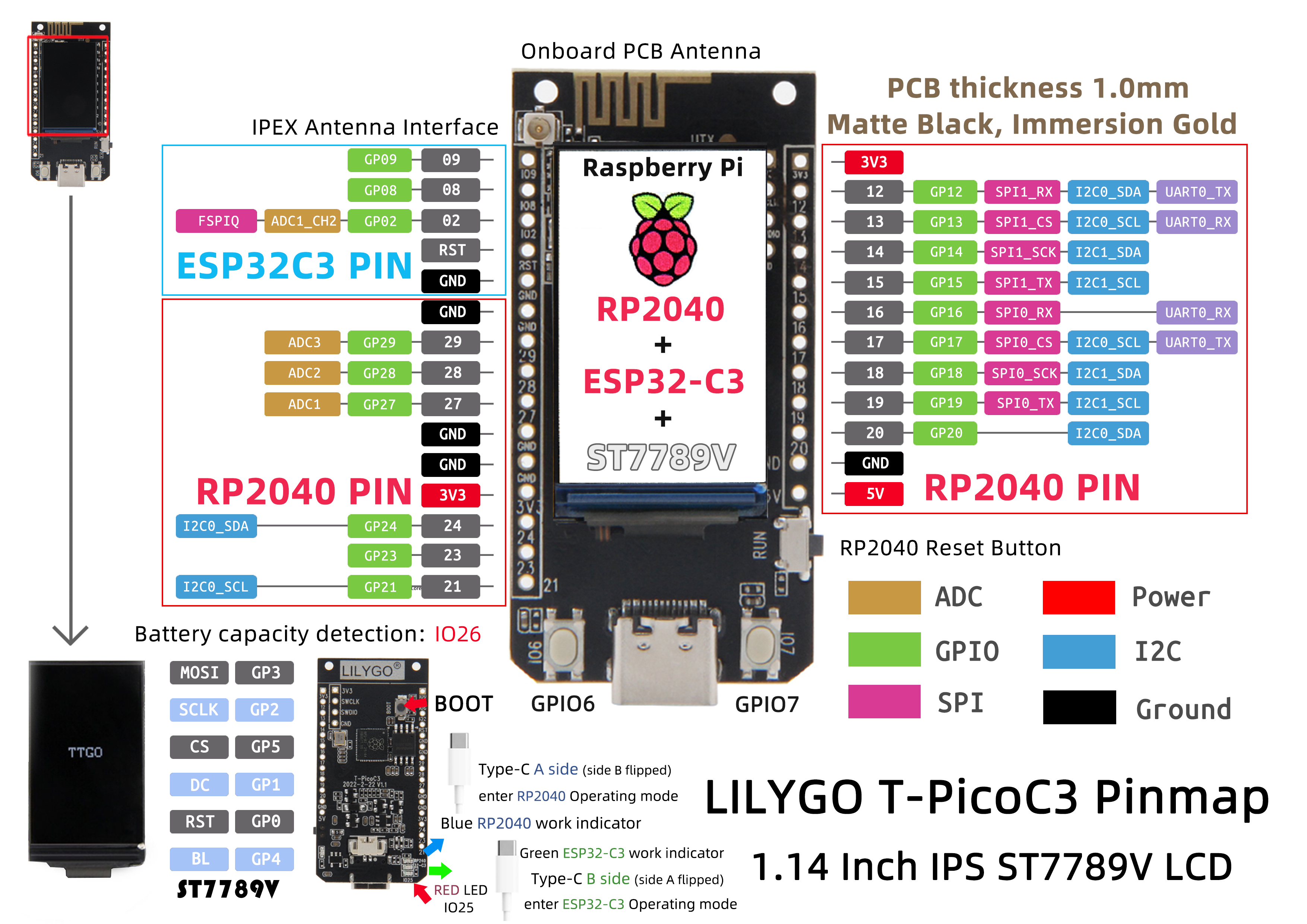
So on one tiny PCB, they deliver the dual-core+specialized bit-banging capacity of RP-2040 (which has been used to bitbang DVI (!) and countless light chasers based on WS2812, which is a protocol with odd timing requirements) with the ESP32-C3 seemingly left to handle a full TCP-IP stack, Bluetooth, compression, security, and other such tasks while “additionally” being a quite capable 160Mhz RISC-V core of its own.
Putting “the two great tastes that taste great together” sounds like a good idea (let one chip specialize in networking, two RP2040 PIO bit cores blink out a CAN bus or 2812 (or other) LED blinkies) and hold it all down with some MicroPython on either (or both) of the Cortex M0 cores. Whether you’re a student that really just wants to backpack a single board for both ARM and RISC-V programming or you’re building a robotics or IoT thing, it’s just easy to imagine these going well together. You can make crazy combinations of dedicated interrupt controllers, GPIO controllers, interrupt domains, etc. MIx them up as you see fit.

Debugging your creation
Normally, for ease of debugging, I nod to the ESP32-C3. Inside the part are dedicated cores that run a FTDI-like parallel controller that can be used for JTAG debugging AND a USB communications class, so your device’s serial console can appear on the same plug you’re powering the unit from. For someone that values mobility while debugging, it’s awesome. So those are the obvious connections for the USB lines.
But how do you debug the RP2040?
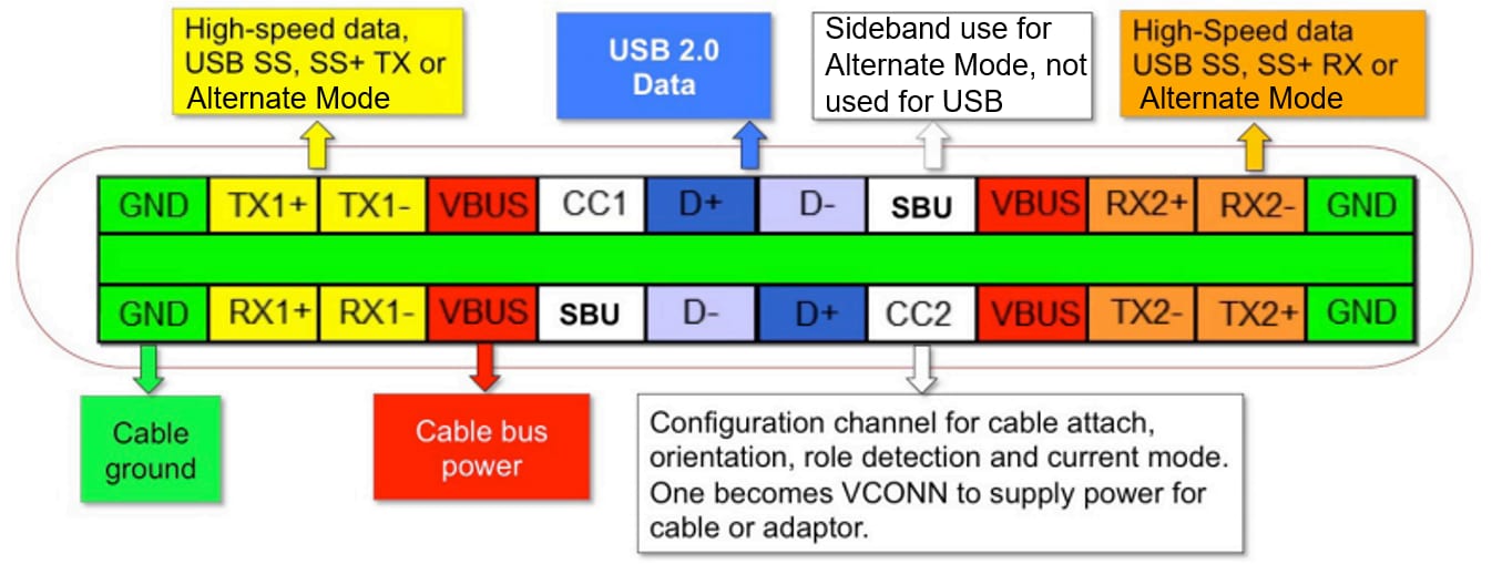
I’m normally a big fan of USB-C. Beyond the speed, the power – both in literal volts and amps and in the capacity of devices you can attach – I dig that they can be flipped end for end (no “host” and “target” end) and that they can be flipped from top to bottom, making them impossible to plug in upside down. The receptacles are symmetric. Compliant USB-C cables are only kind symmetrical. It’s lesser known that the tops and the bottoms of the plugs are actually not fully asymmetrical. The controllers actually engage in strategic lies that pull off the flippability trick. These same strategic lies are what allows the cables to smuggle additional kinds of data, such as Thunderbolt signals or GPIO and JTAG pins in the case of the breakout board for Pine64‘s Pinecil. Even with these mistruths, it’s common practice to uphold the guidelines for the cable to work either way.
Do you hate your users?
For a hybrid board like we’ve described above where we’re trying to attach two quite different SoC’s to the host, the “obvious” thing to do would be to add something like CH340 to give USB powers to the RP2040 console. Then you add a USB hub and tie both chips behind the hub, allowing all three devices to appear to the host. A more sophsticated design might tie the 2040 instead to a serial from the ESP32-C, but then you lose USB-master mode for the 2040. A circuit-layout Jenga master may have been able to find a USB-C pinout that let one device ride shotgun on the bus of another along the approach of the Pinecil’s exposed JTAG lines but I think that has compromise if you’re pretending to be a host instead of a target. Instead, we’re left to imagine this conversation happening within LilyGO’s engineering:
“What if we built an interface that worked completely differently if plugged upside down?”
“Why would you build a Cursed USB-C device? Do you hate your users?”
“What if we made it blink different colors, but unreliably?”
“OK.”
So our imagined engineers dutifully run off and after a little USB Selective Disobedience, successfully deliver power and ground – safely – in either orientation. (That’s the red and green in the below diagram and that’s intentionally made infallible.) With one mating between the cable and the board, the ESP32 has ownership of D+ and D- so the JTAG and serial ports associated with the RISC-V side of the house are presented to the host. You can use esptool to program and manage that device or program it via JTAG. In the other orientation, RP2040 gets the port and it’s either a USB mass storage device awaiting a .uf2 boot file to chomp on or a connection from the Thonny Python IDE.
Imagine the top (“blue led”/RP2040) being attached to the top D+/D= pair on the right and the bottom (“Red LED”/ESP32-C3) being attached to the bottom D-/D+ pair.
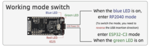
Great. Now we’ve created a product that works exactly like a ‘normal’ user would never expect it to work, but, given the target audience, this is probably OK. Only it leads to hilarious disclaimers like this:
When connecting, the onboard LED lamp will be indicated according to the connected chip (due to cable problems, it is possible that the indicator light is opposite to the actual connected chip, or even two LED lights at the same time, please replace another cable when two led lights up at the same time)
The moral(s) of this story
 No, no, no. Those are morels. They’re different.
- LilyGo makes some pretty cool stuff. Their products aren’t necessarily destined for “Raspberry Pi” levels of creativity and ubiquitousness, but they have some nifty and fun mixups that can save a budding EE (or a struggling SWE) from rolling their own designs. Many of their products are straight-forward mashups of existing low-cost circuits, but on one convenient board. Not everything needs to be complicated to be useful.
- Sometimes, there just are not points awarded for style. It’s easy to imagine a $15 product that may spend a semester or two inside a students backpack or a one-off that’s inside your IoT robot that needs both WiFi and finely controlled WS2812 “lasers” – or, heck, real lasers cutting into or measuring something. These may be programmed less than a dozen times before they’re retired (the first case) or sent into duty and unlikely to be connected to a PC ever again (the second case) As long as the users are in on the ‘joke’ that a cable that should never need to be flipped sometimes needs to be flipped, maybe that’s OK. Making that connection twice as reliable but requiring twice as many cables, a hub, defining the interaction of all these devices potentially controlling the bus at the same time, etc. is money you’ll never get back.
- It’s absolutely not, however, OK to do this to an end-user, mass produced product unless you do, in fact, hate your users. (Hint: they will retaliate somehow….) Consumers want standard things to work in standard ways.