Issues with USB-C powered development boards
Below – Hall of Shame:
The symptom: dead boards
More than once in my development time, I’ve been an early receiver of a development board that powers via USB-C. Invariably, the board is so new that there is no documentation provided with the board and little to nothing already existing on the web about it – after all, helping create some of that documentation is probably why I have the board. There may be no source code, no schematics, and no doc. I’m even pretty liberal in accepting early development documentation in Chinese – Google Translate is pretty amazing on technical material and Google Lens can help crack the case of all-too-common case of Chinese text baked of images. (This is bad for accessibility, such as screen readers or even visual assists that may beed to expand text and be able to do a reflow…but that’s a different rant.)
For first power-up, there’s not really an expectation of any code being flashed into whatever kind of flash memory is available. With SMT LEDs bragging about being .8 or even .65mm, it’s far from given that I’ll recognize an LED on the board at all just by visual inspection and even at that scale, silk-screens don’t much work, so the parts aren’t likely labeled. Similarly, there are often not recognizable chips on the boards that set expectations of how it should act if successfully connected. Sure, if there’s an FTDI 232H or a CH340, we can know to look for a USB serial device enumerating on the host PCI bus. However, microcontrollers like the ESP32-C3 or BL706 integrate USB right on the chip and may or may not implement USB CDC protocol, While that’s awesome for development (hooray, it’s a disk drive and I can just copy firmware to it!) it means you can’t depend on the visual cue of a Finder window popping open when the board is recognized.
This is a lot of words to provide background to the lede I’ve already buried in the title. The short version is that it’s not totally unexpected to connect a board and have exactly no visual confirmation the board is running and no recognizable signs of life from the computer.
In addition to all the above possible causes (no LEDs, no code flashed, required external boot knocking sequence required, no boot device present, device permanently in reset because it’s a jumper not a button (yes, really) there’s another that’s far more frustrating: the board developer did not read and understand the USB-C specification.
The cause: a poor understanding of USB-C
USB-C is more than USB 3.1 in a flippy connector, though that is undeniably nifty. It fundamentally changes how power is transferred over the wire because it allows bidirectional charging as well as bidirectional signaling (formerly “USB On The Go”) but because there’s way power potentially involved, particularly because it’s the first time more than 5v may be present on the power rails. Failure to handle USB-C’s power requirements correctly can result in 24VDC being sent to your 25 year old floppy drive that was built into a 5V-only world and that’s bad.
For older USB, you could always count on at least 100mA of 5V on the power rails. As a practical matter, you could count on 500mA from most devices even without explicitly enumerating on the bus or even 900mA starting with USB 3.0. For lots of tiny development boards, that’s all plentiful.
On USB-C, there are two new pins on the bus named CC1 and CC2. If you have a device that may either provide or receive power (your laptop or your phone can charge your earbuds, but they can be charged over the same plug) then you need a Real USB controller chip like an STM32 or a MAX77958 on the bus and you need a real EE that can read and understand the relevant specs in order to implement your Dual Role Port as that’s a more complicated case than a Sink Port (a load) or a Source Port.
A compliant USB-C Power Delivery Source Port (e.g. a high-quality USB-C charger or a laptop with actual USB-C jacks) will monitor the CC1 and CC2 pins for voltages, nominally provided by a pair of resistors forming a voltage divider. The presence of a pair of 5.1k resistors (at a cost of a fraction of a penny in quantity to tie each of CC1 and CC2 to ground ) tells the power supply to deliver 5V at 3A.
If your device has a USB-C jack and does NOT provide those two resistors, the USB Power Source is under no obligation to provide power to your device. Your device will be unpowered and, most likely, will not work.
The full USB-C and related specs run into thousands of pages and this is probably just caused by misunderstanding that USB-C is just like its predecessors. Fortunately, there are good descriptions like this primer from ST on implementing USB-C power.
“But it works on my PC”
If you have a USB-A to USB-C cable, it is known there can be no bidirectional charging so the resistors are present in the cable.
“Can I save an eighth of a cent and use one 5.1K resistor instead of two?”
No. Raspberry Pi foundation learned this very publicly and frustrated thousands of customers in the Raspberry Pi 4 defective USB implementation.
“But it almost works if I do it…”
It works except when it dosn’t. It may fail on e-marked cables (very common amongst uses of high-quality, high-power gear) but actual experts can explain why you need two individual 5.1k resistors on USB-C devices. Googler Benson Leung made a substantial name for himself in the early days of USB-C popularity by buying a large variety of USB-C cables and devices, finding that spec compliance was farcical, and working with Amazon to improve quality of devices in the marketplace.
“But that’s an old problem. Nobody would build a board without those resistors today.”
Pi 4 was just a high-profile early victim. Boards with this problem are still rolling out.
Allwinner Nezha
Sipeed engineering confirmed that the Allwinner Nezha RISC-V development board does not pulldown CC1 and CC2. That port is theoretically bidirectional and should thus use an actual USB PD controller chip because it will not boot from a USB-C power source.
Bouffalo Labs BL706 AVB
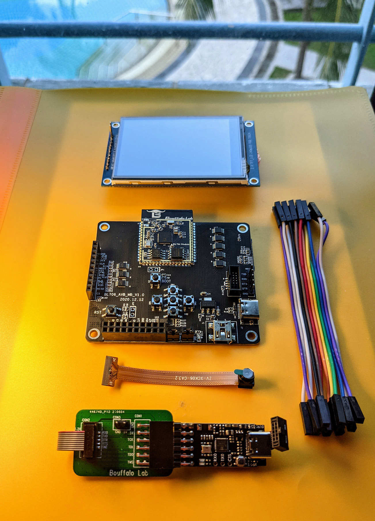
The Bouffalo Labs BL706 Audio Video Board does not provide those resistors, presumably for similar reasons. The board will not boot from USB-C.
WCH CH32V307 EVT
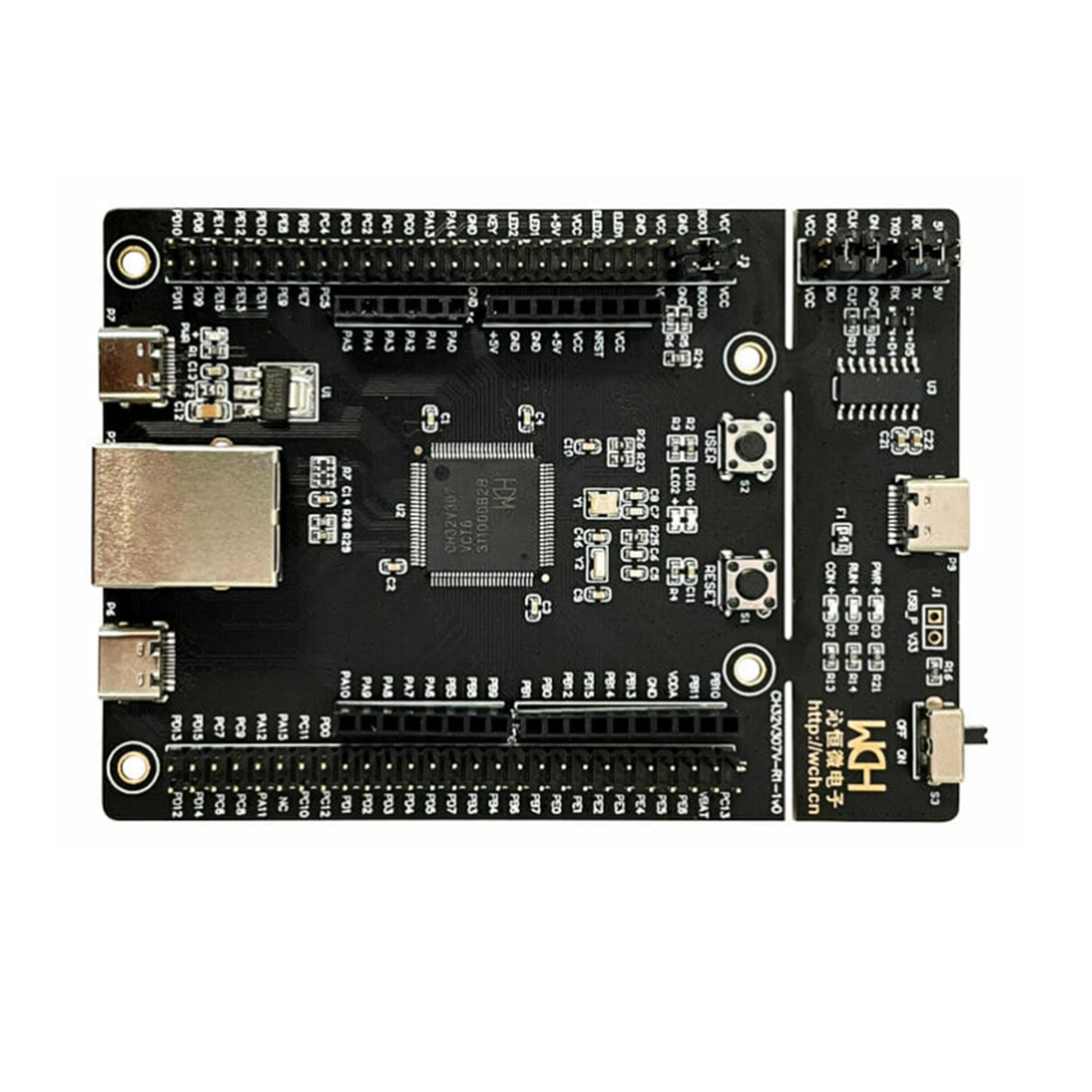
The WCH CH32V307 EVT board provides empty soldering pads on the back of the board at R9 and R10 for you to add your own to the debug port . Without them, the CH32V307EVT will not boot from a USB-C power source. That design choice is a bit strange because while similar pads are provided for the full speed and high speed jacks (which could be hosts or device) the WCH-Link port looks like it can be only a device
I have a board like that! I’m not an EE What can I do?
As ridiculous as this sounds, the lowest cost, easiest way to work around this is to use a USB-C to USB-A adapter (a hub will work, too, but will be more expensive if you’re shopping) and then a USB-A to USB-C cable. The result is to have a cable with USB-C on both ends, but a mail and female USB-A in the middle. That will add the ressistors in question and all three of the boards above will successfully boot from a USB-C Power Delivery power supply OR directly from the port on a MacBook Pro.
Share your war tales
Do you have a board like this? Share below to help get the word out that it’s not 2014 and partially implementing USB-C is Not OK.