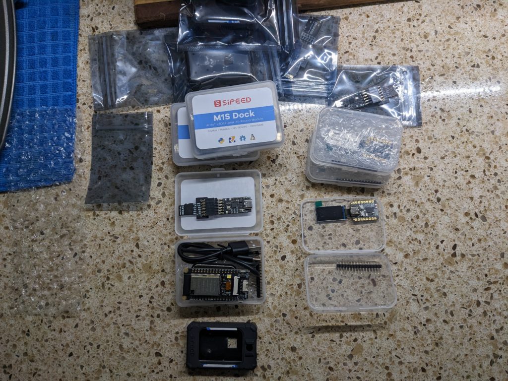
The much anticipated products from Sipeed, The M1S Dock and M0 Sense are now being delivered to customers. Mine arrived in the U.S on December 20, to my surprise as the tracking number never fired on USPS Informed Delivery and Fedex did not announce the delivery. These were purchased boards and are not prerelease.

M1S Dock

M1S Dock is a board with the Bouffalo BL808 Processor. It features three RISC-V cores: one 480Mhz 64-bit -T-head D906 variant that’s similar to the one in Allwinner’s D1 (including the outdated 0.7.1 vector unit, alas), one 320Mhz T-Head 32-bit E907 for coprocessing, and one low-power 150 Mhz T-Head RV32EMC core for super low power use, such as keyword recognition to awaken the others on demand. As a bonus, it contains NPU BLAI-100 (Bouffalo Lab AI engine) for video/audio detection/recognition.

The M1S Dock starts at $10.80 for the board with headers and ranges to $24 with camera, LCD, and case.

The device supports:

  • 2.4 GHz 802.11 b/g/n Wi-Fi  4
  • Bluetooth 5.x dual mode (classic + BLE)
  • IEEE 802.15.4 for Zigbee
  • 10/100M Ethernet through add-on board

There is 64MB of RAM and a “real” MMU with RV32, so while you’re not going to run your favorite Fedora workstation-class configuration on it, a ‘normal’ embedded Linux kernel and supporting utilities is quite practical.

Optional peripherals from Sipeed, pictured below, include the display, a debug board (which features yet another RISC-V part, the BL706, to bit-bang the debug protocol (which appears to NOT be JTAG), a camera, and a hard plastic case.

Image of M1SDock and M0Sense
M1SDock and M0Sense

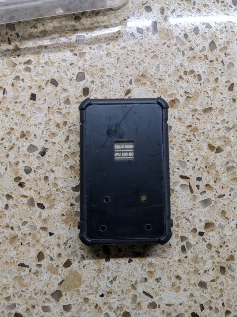
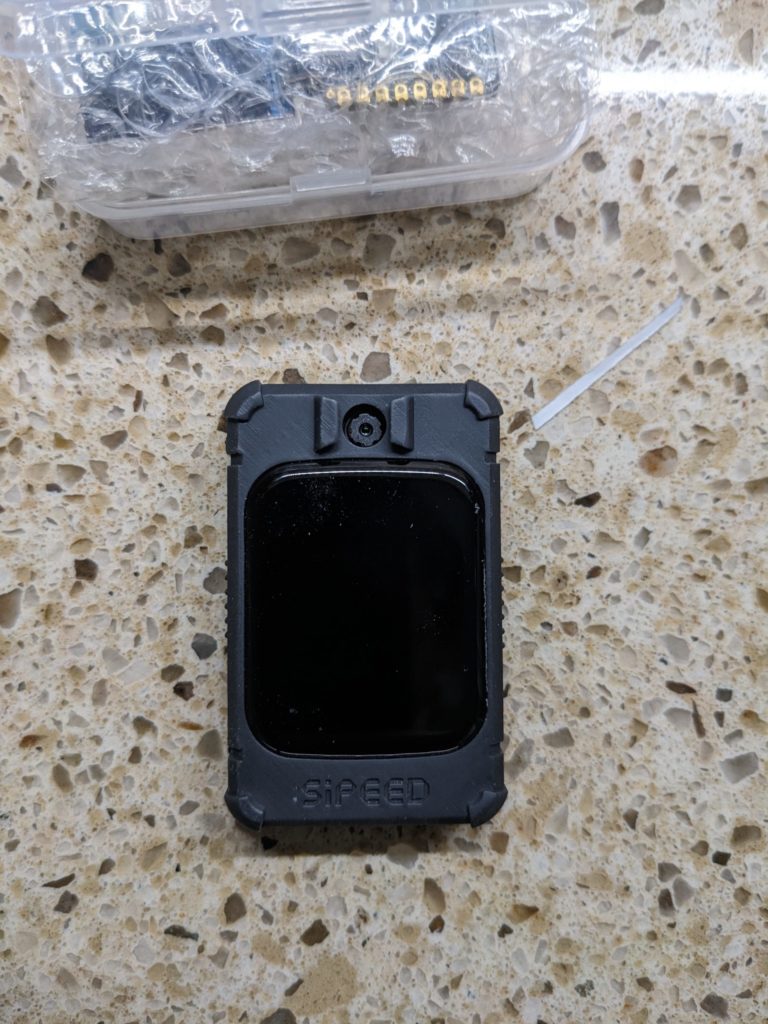
Assembling the case is best described as painful. While it looks like a flexible silicone case, it’s not. It’s a hard plastic with a rubbery texture. The screen has to be removed from the double-stick tape holding it to the board, have the screen passed through the hole, have the screen fastened to the board, and then the board threaded into the case. Since the double-sided tape for the screen has a small area, I’m not expecting to be able to remove and re-insert the screen very many times.  If I’d known what a pain it was, I wouild have certainly soldered down the provided .100 posts before mounting it.

Image of Back of M1s Dock
Back of M1s Dock
Image of Front of assembled Sipeed M1s Dock
Front of assembled Sipeed M1s Dock


Sipeed has done well providing documentation for the M1S Dock, including pinouts, a full SDK (with Bouffalo Labs) , AI Model and Framework, and a handy drag & drop approach to burning firmware. and many M1S Dock demos.

M0 Sense

Also delivered are the M0Sense boards. These are a lovable little alternative to nRF52480-class hardware. The featured processor is the BL702 at 144Mhz. Twelve of the sixteen pins are available I/Os and the board comes with Bluetooth, including BLE. The SiFive core is attached to 132K of ram and 512K of flash. The board provides an IMU and a USB Full-speed (12Mbps) interface. Computationally they may not take the dual-cores (and PIO) of the RP2040 products, but these are great alternatives in the RISC-V world that offer easy programming and plenty of powerful I/O.

The board starts at $4.50 USD. Adding the .96 screen makes it $5.99.

Sipeed has done well providing documentation for the M0Sense, including pinouts, a full SDK (with Bouffalo Labs) , AI Model and Framework, and a handy drag & drop approach to burning firmware. and many M0 Sense demos.

Summary

Between these boards, you have a very low-end sensor board with ML abilities for $4 that includes I2C, SPI, and all the normal things to connect to your own sensors AND a relatively high-end MCU with a dedicated ML coprocessor. With M1S Dock being a cousin to Pine64’s OX64, we’re sure to see a ton of software development around them. They’ve taken the sharp edges of Bouffalo’s unpleasant boot loader by providing a drag-and-drop capable boot loader. The BL808’s available RAM, performance, and price really makes it difficult to lean into the Kendryte K210 class of boards as we enter 2023.

I really look forward to exploring these boards in coming weeks and months. What do you plan to do with them?

Issues with USB-C powered development boards

Below – Hall of Shame:

The symptom: dead boards

More than once in my development time, I’ve been an early receiver of a development board that powers via USB-C. Invariably, the board is so new that there is no documentation provided with the board and little to nothing already existing on the web about it – after all, helping create some of that documentation is probably why I have the board. There may be no source code, no schematics, and no doc. I’m even pretty liberal in accepting early development documentation in Chinese – Google Translate is pretty amazing on technical material and Google Lens can help crack the case of all-too-common case of Chinese text baked of  images. (This is bad for accessibility, such as screen readers or even visual assists that may beed to expand text and be able to do a reflow…but that’s a different rant.)

For first power-up, there’s not really an expectation of any code being flashed into whatever kind of flash memory is available.  With SMT LEDs bragging about being .8 or even .65mm, it’s far from given that I’ll recognize an LED on the board at all just by visual inspection and even at that scale, silk-screens don’t much work, so the parts aren’t likely labeled. Similarly, there are often not recognizable chips on the boards that set expectations of how it should act if successfully connected. Sure, if there’s an FTDI 232H or a CH340, we can know to look for a USB serial device enumerating on the host PCI bus. However, microcontrollers like the ESP32-C3 or BL706 integrate USB right on the chip and may or may not implement USB CDC protocol, While that’s awesome for development (hooray, it’s a disk drive and I can just copy firmware to it!) it means you can’t depend on the visual cue of a Finder window popping open when the board is recognized.

This is a lot of words to provide background to the lede I’ve already buried in the title. The short version is that it’s not totally unexpected to connect a board and have exactly no visual confirmation the board is running and no recognizable signs of life from the computer.

In addition to all the above possible causes (no LEDs, no code flashed, required external boot knocking sequence required, no boot device present, device permanently in reset because it’s a jumper not a button (yes, really) there’s another that’s far more frustrating: the board developer did not read and understand the USB-C specification.

The cause: a poor understanding of USB-C

USB-C is more than USB 3.1 in a flippy connector, though that is undeniably nifty. It fundamentally changes how power is transferred over the wire because it allows bidirectional charging as well as bidirectional signaling (formerly “USB On The Go”) but because there’s way power potentially involved, particularly because it’s the first time more than 5v may be present on the power rails.  Failure to handle USB-C’s power requirements correctly can result in 24VDC being sent to your 25 year old floppy drive that was built into a 5V-only world and that’s bad.

For older USB, you could always count on at least 100mA of 5V on the power rails. As a practical matter, you could count on 500mA from most devices even without explicitly enumerating on the bus or even 900mA starting with USB 3.0. For lots of tiny development boards, that’s all plentiful.

On USB-C, there are two new pins on the bus named CC1 and CC2. If you have a device that may either provide or receive power (your laptop or your phone can charge your earbuds, but they can be charged over the same plug) then you need a Real USB controller chip  like an STM32 or a MAX77958 on the bus and you need a real EE that can read and understand the relevant specs in order to implement your Dual Role Port as that’s a more complicated case than a Sink Port (a load) or a Source Port.

A compliant USB-C Power Delivery Source Port (e.g. a high-quality USB-C charger or a laptop with actual USB-C jacks)  will monitor the CC1 and CC2 pins for voltages, nominally provided by a pair of resistors forming a voltage divider. The presence of a pair of 5.1k resistors (at a cost of a fraction of a penny in quantity to tie each of CC1 and CC2 to ground ) tells the power supply to deliver 5V at 3A.

If your device has a USB-C jack and does NOT provide those two resistors, the USB Power Source is under no obligation to provide power to your device. Your device will be unpowered and, most likely, will not work.

The full USB-C and related specs run into thousands of pages and this is probably just caused by misunderstanding that USB-C is just like its predecessors. Fortunately, there are good descriptions like this primer from ST on implementing USB-C power

“But it works on my PC”

If you have a USB-A to USB-C cable, it is known there can be no bidirectional charging so the resistors are present in the cable.

“Can I save an eighth of a cent and use one 5.1K resistor instead of two?”

No. Raspberry Pi foundation learned this very publicly and frustrated thousands of customers in the Raspberry Pi 4 defective USB implementation.

“But it almost works if I do it…”

It works except when it dosn’t. It may fail on e-marked cables (very common amongst uses of high-quality, high-power gear) but actual experts can explain why you need two individual 5.1k resistors on USB-C devices. Googler Benson Leung made a substantial name for himself in the early days of USB-C popularity by buying a large variety of USB-C cables and devices, finding that spec compliance was farcical, and working with Amazon to improve quality of devices in the marketplace.

“But that’s an old problem. Nobody would build a board without those resistors today.”

Pi 4 was just a high-profile early victim. Boards with this problem are still rolling out.  

Allwinner Nezha

Sipeed engineering confirmed that the Allwinner Nezha RISC-V development board does not pulldown CC1 and CC2.  That port is theoretically bidirectional and should thus use an actual USB PD controller chip because it will not boot from a USB-C power source.

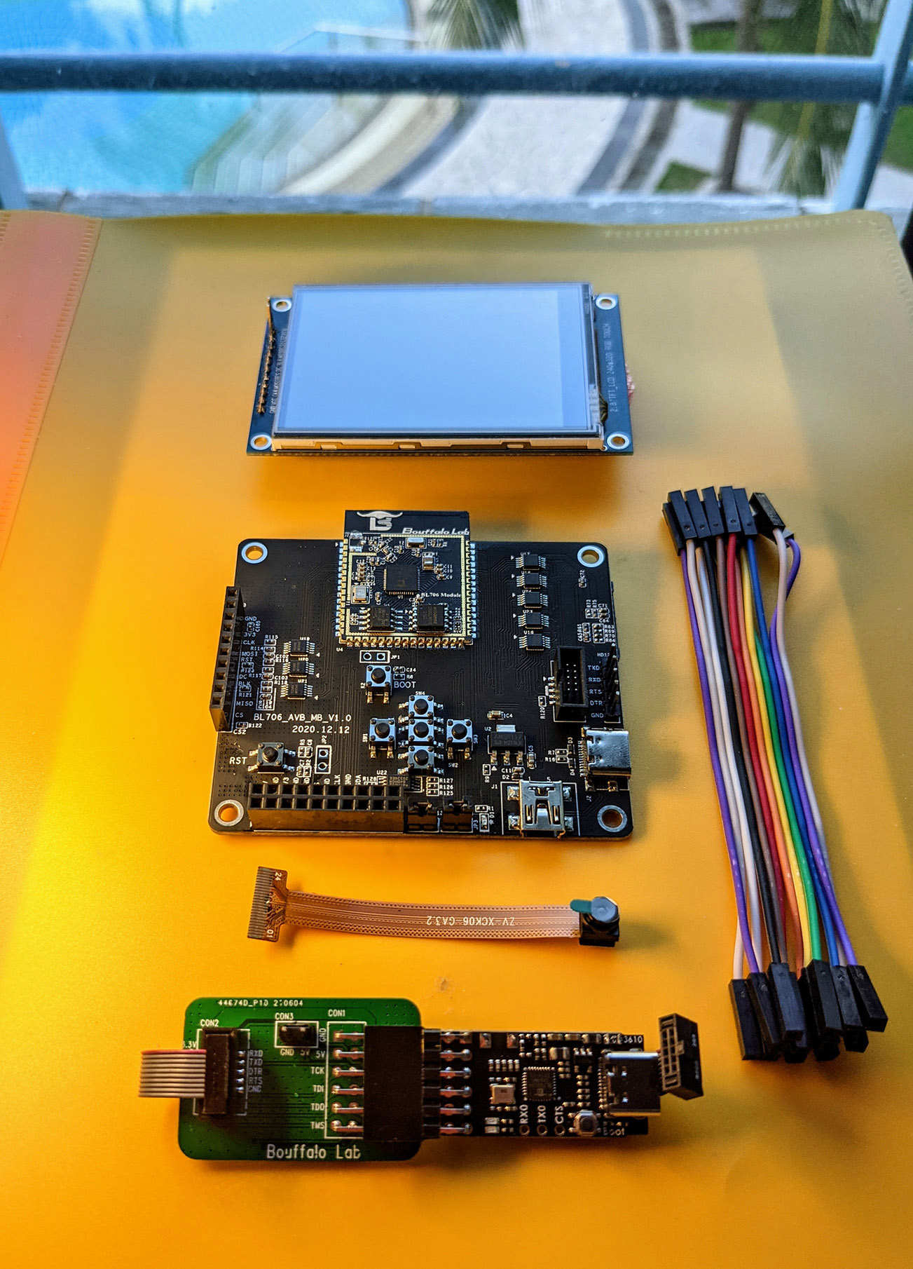
Bouffalo Labs BL706 AVB

Dev Kit for Bouffalo Lab BL706 Audio Video Board
The Bouffalo Labs BL706 Audio Video Board does not provide those resistors, presumably for similar reasons. The board will not boot from USB-C.

WCH CH32V307 EVT 

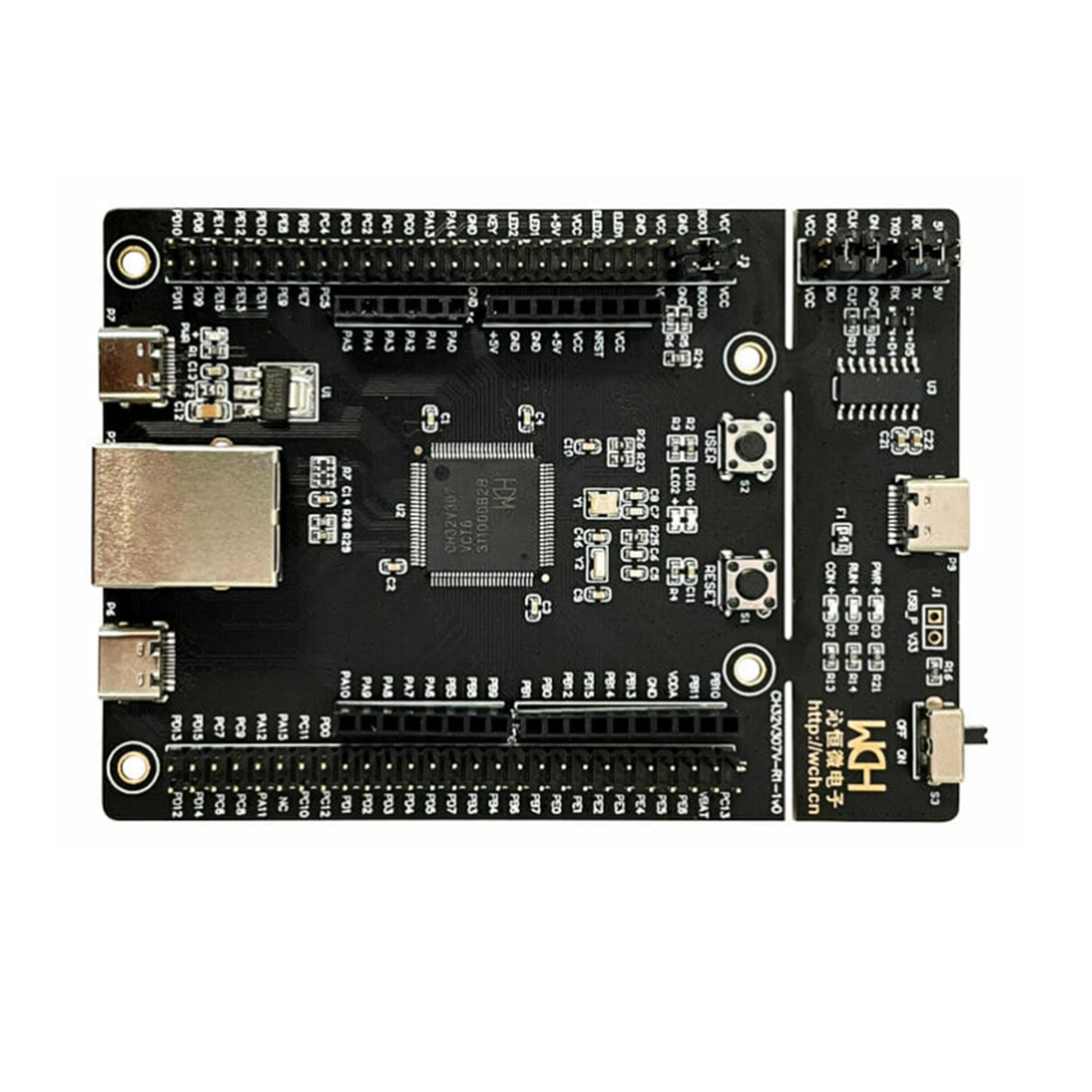
CH32V307V-EVT-R1 RISC-V development board
The WCH CH32V307 EVT board provides empty soldering pads on the back of the board at R9 and R10 for you to add your own to the debug port . Without them, the CH32V307EVT will not boot from a USB-C power source. That design choice is a bit strange because while similar pads are provided for the full speed and high speed jacks (which could be hosts or device) the WCH-Link port looks like it can be only a device 

I have a board like that! I’m not an EE What can I do?

As ridiculous as this sounds, the lowest cost, easiest way to work around this is to use a USB-C to USB-A adapter (a hub will work, too, but will be more expensive if you’re shopping) and then a USB-A to USB-C cable. The result is to have a cable with USB-C on both ends, but a mail and female USB-A in the middle. That will add the ressistors in question and all three of the boards above will successfully boot from a USB-C Power Delivery power supply OR directly from the port on a MacBook Pro.

Share your war tales

Do you have a board like this? Share below to help get the word out that it’s not 2014 and partially implementing USB-C is Not OK.

About this article: This preliminary attack on Buttons on BL60x with Nuttx can be thought of as an article that’s part of Lup’s Book on BL606 generally and his notes on Nuttx on BL60x specifically. As I was the one that made this experiment, I documented it for the rest of you. As a spoiler, the experiment failed, but we learned important lessons along the way and THOSE lessons are worth sharing more than the actual resulting button work.

Electrical switches, or in their more passing form, buttons, are as simple as it gets electrically. A button is like a piece of wire: it’s connected or it is not. It closes the circuit or it doesn’t. Mechanically, switches can take many forms like normally open (the wire is missing until it’s physically operated) or normally closed (pressing it removes the connection).

On the PineDio Stack, we have one push button that is connected to our BL604 SoC.. The push button is next to the internal LEDs and is connected internally to GPIO12.
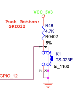
Schematic of GPIO_12 on PineDio

From the schematic, we see that GPIO12 is connected via a 4.7k resistor to the power rail. When open, the naturally resting position of this button, GPIO is left to float high because it’s wired to VCC via the R48 pullup resistor. This provides enough resistance to deliver voltage to prevent that pin from floating and is enough resistance that when we close pushbutton, driving GPIO12 to ground, we don’t risk the steadiness of our power source by shorting it even temporarily to ground.
PineDio Stack Bootstrap schematic

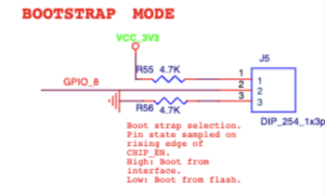
There is actually a second switch available in PineDio stack, but a bit subtle – in fact, by default, it’s missing! The GPIO8 pin that we jumper on boot is actually a form of a button. Whether by a button or a jumper, it can be connected to either the voltage source or the ground, Natively, that jumper/switch is read exactly once during bootup so the flash firmware can decide whether to run the flash reader or to run your code. As this tale isn’t about GPIO8 – indeed, using GPIO8 in your own designs would be questionable as closing that switch during power-on would result in your product “not booting” to the untrained eye – we shall ignore the GPIO8 pseudo-switch.

From the view of the BL604, our button on GPIO12 is an input and it is upon us to (somehow) configure it as such. We’ll take responsibility for that in a minute. We either read the +3.3V in the normal case or we read the 0V of ground when the button is pressed.

Each GPIO (16 on the BL602 and 23 on the BL604) can be configured as:

• Floating input
• Pull-up input
• Pull down input

• Pull-up interrupt input
• Pull-down interrupt input • Floating interrupt input
• Pull-up output
• Pull-down output

Our hardware designer here has helpfully provided us with external pull-ups to +3.3V, so we’ll configure it first as floating input and just read the button by polling it. This is OK if you’re accessing the button frequently or it’s a major component of your application’s life cycle. For example, the joystick buttons on PacMan are pretty much always being pressed in one direction and the game is doing little if it’s not, so it’s OK to dedicate the CPU to checking the buttons. A more typical application, which we’ll attempt later, lets the CPU receive an interrupt when the button status changes. For a stopwatch button or a screen menu change, that is a much more typical use as it frees your program execution from polling the button all the time.

Elsewhere in the schematic, we also see that the GPIO_12 pin can be used as an output to control the vibrator. We’ve since learned that option isn’t actually populated on the devices in our hands, so we’ll largely ignore the output options on GPIO_12.

Our BL602_BL604_RM_1.2_en Reference Manual has many dozens of pages dedicated to explaining how the GPIO pins work in great detail. While it’s perhaps helpful to know all the details (could the board designer have saved the cost of the pullup resistor if “Pull-up input” mode were known?) we will instead rely not only upon the GPIO functions of Nuttx, we will rely on the “Button” specializations.

In general speaking, there are two ways for a CPU to notice a change on a signal: it can generate an interrupt or it can poll that signal. For super precise timing or when the CPU has nothing else to do, polling is often preferred. For thing like a pushbutton that change quite infrequently, a processor interrupt is usually a designer’s choice.

The Nuttx Apps project provides an example Buttons app in apps/examples/buttons/, which is quite rich in features, but it can also be a bit overwhelming. We’ll instead create a smaller case more specialized for our hardware.

We set out to create a Nuttx application (not a driver) to learn about the button state. As such, we’d interface with the buttons through special files in /dev instead of using BL602-specific functions.

First, we confirm that we have Nuttx building and runnable on our hardware. Our /dev entry contains generic GPIO, but we need to specialize it.

ls /dev
/dev:
console
gpio0
gpio1
gpio2
i2c0
lcd0
null
spi0
spitest0
timer0
urandom
zero

Because we’re several episodes deep into these tutorials, we’ll touch on the steps, but not the details to wire up a new example. The recipe is very much the same as in the other chapters of the BL602 book.

$ cd apps/examples
$ mkdir button_test
$ cp tinycbor_test/* button_test
[ do a bunch of mechanical edits to make a “new” program - we’re sharing that here, so you don’t have to repeated it. ]
KConfig, Makefile are nearly a search and replace.
Button_test_main.c starts empty, with only a main() returning 0.

Instead of hand-editing things, we turn ourselves into the build process for now.
$ kconfig-tweak –enable CONFIG_EXAMPLES_BUTTON_TEST
$ make olddefconfig
$ make -j20

Perform a flash update, upload the program, and restart the demo
On the device, confirm that we’ve successfully linked our new build. Notice the presence of button_test:
# Builtin Apps:
bas i2c sh
bl602_adc_test ikea_air_quality_sensor spi
button_test lorawan_test spi_test
[ … ]

Now let’s start configuring our hardware.

Because GPIO in BL60x is currently in a transitional state, we’re just going to brute-force ourselves into the first entries. So in ./boards/risc-v/bl602/bl602evb/include/board.h we’ll just temporarily take over that slot from PineDio Stack. This is clearly not great for interoperability, but it sidesteps a number of issues that MisterTechBlog is already working on .


kconfig-tweak --enable CONFIG_ARCH_BUTTONS
kconfig-tweak --enable CONFIG_ARCH_IRQBUTTONS

N.B. These are included in our provided defconfig for this board, but for reasons I don’t understand, we still have to manually set them here to be effective.

make oldconfig

Rebuild Nuttx and reflash it to the board as you have in the other articles to follow along.

The best-laid plans of mice and men often go awry

Our original plan was to interface with the switch in all three ways that Nuttx knows how to do this, but the wheels fell off that idea while we were building it. (Yes, we did have wheels while we were building it because Lup and and I were consulting with each other and tag-teaming development, each working on different aspects.) If we did all this right, there would actually be nothing BL602-specific exposed in our test application and we’d have validated all our internal private handling. That latter bit was a success, in an awkward way – we validated that they didn’t work.

The three approaches are:

    1. Read the GPIO pin “raw”. Just open the device, read it, and report the status.
      Configure the GPIO interrupt facility to let main() in our application do something else – or nothing else, such as just being in a sleep().
    2. Configure the Nuttx GPIO interrupt infrastructure. Success ultimately relies on an upper half running in application space and a lower half running in kernel space to deliver this interruption of event flow to the application to hop out to registered function names and handle these events.
    3. Configure the Nuttx button infrastructure, configured via CONFIG_ARCH_IRQBUTTONS to deliver an asynchronous event into the application to interrupt the flow and tell it that a button close or open event has been made. This actually relies on the above internally to work.

For any of these to work, we have to tell Nuttx where our buttons are we do this in board.h with an entry like this:

    #define BOARD_GPIO_INT1 (GPIO_INPUT | GPIO_PULLUP | \
        GPIO_FUNC_SWGPIO | GPIO_PIN12)

Get to the code!

While the order in the provided sample program flows slightly differently than is described, it’s hopefully recognizable. (The code is structured as it was to reduce repetition when we presented this in three different approaches.)

There’s no magic in dump_buffer(). It’s fortified to protect a (human) debugger from printing control characters or lengthy buffers directly to the screen, but it’s quite simple:

static void dump_buffer(const int buf_size, const char* buf) {
    for (int i = 0; i < buf_size; i++) {
        printf("%02x(%c) ", buf[i], isalnum(buf[i]) ? buf[i] : '.');
     }
}

Raw GPIO reads is the simplest.


int fd = open(INPUT_DEV_NAME, O_RDONLY);
for (int pass = 0; pass < count; pass++) {
  char ibuf[20];
  printf("Pass %d of %d:", pass, count);
  int c = read(fd, ibuf, sizeof(ibuf) - 1);
  dump_buffer(c, ibuf);
  if (c > 0) {
    if (ibuf[0] == '0') {
        printf("- Pressed");
    }
  putchar('\n');
}
lseek(fd, 0L, SEEK_SET);
usleep(500000);
close(fd);


This simply checks if the GPIO pin is active, printing anything we get from the GPIO port in hex and in ASCII and adds “active” if so. By default, we check the button rather arbitrarily 20 times and we sleep half a second between passes. This provides a nice feedback loop allowing you to press and release the button a few times and see the screen change in response.

There are really only two lines that may be worthy of surprise. First, the data as we display in dump_buffer() and as we test in the zeroth byte of ibuf[] is not a binary 0 and 1 as you might expect. They are ASCII ‘0’ and ‘1’ (0x30 and 0x31) respectively. This might be a bit surprising to those experienced with device driver handling as you might expect a more raw 0 and 1 there. This is actually a peace offering to command-line users of the GPIO drivers; it’s simply convenient to be able to cat (or hexdump or read…) a port and see its status. It’s similarly convenient to be able to write to it via ‘echo 1 > /dev/whatever’ to blink an LED or start a motor or anything else that may be an output on this same driver. So the ASCII convention actually is convenient here.

The second potential sharp edge is that streaming reads of the GPIO node will not stream reads. You may expect to ‘cat /dev/gpioin0’ and see a stream of 1s until you press the button, at which point you’d see a stream of zeroes until you released the button. Adjust your expectation. Again, presumably for compatibility with command line tools that keep a short lifecycle of a device’s file descriptor, only the very first byte of that potential bytestream is ever valid. You could close and reopen the device to get back to the beginning, but that’s a bit costly as it increases the total number of potential system calls, the transitioning edge between OS application code and kernel mode. We thus use lseek() to just to back to the beginning and read it again.

This is all jolly well and very satisfying. We’ve hooked up a button logically to the operating system and we’re now able to read it and do something useful with it.

“And then, the murders began…”

Filled with confidence, I proceeded to code up the approach of using GPIO interrupts into user applications. Knowing that we needed to ultimately allow for device with way more than the single button on PineDio Stack, we thought about the configuration scheme. The existing scheme is a series of entries in board.h like this:

#define BOARD_GPIO_INT1 (GPIO_INPUT | GPIO_PULLUP | \
GPIO_FUNC_SWGPIO | GPIO_PIN12)

Initially, we ran into problems if the same pin were configured to be both an output and in input. On PindDio Stack, sharing the button with the vibe didn’t seem completely unreasonable. We could, perhaps, keep the port as an input most of the time and only change the direction when we knew we needed that GPIO line to be an interrupt. We’d lose button functionality while vibing, but that didn’t seem so bad. We put a TODO in the code and vowed to come back to that. Still, that killed most of a day to learn that lesson. (Spoiler: you just can’t do that on this chip. You HAVE to reverse the pin.)

We knew the dance between
#define BOARD_NGPIOIN 1 /* Amount of GPIO Input pins */
#define BOARD_NGPIOOUT 1 /* Amount of GPIO Output pins */
#define BOARD_NGPIOINT 1 /* Amount of GPIO Input w/ Interruption pins */

And

#define BOARD_GPIO_IN1 (GPIO_INPUT | GPIO_FLOAT | \
    GPIO_FUNC_SWGPIO | GPIO_PIN10)
#define BOARD_GPIO_OUT1 (GPIO_OUTPUT | GPIO_PULLUP | \
    GPIO_FUNC_SWGPIO | GPIO_PIN15)
#define BOARD_GPIO_INT1 (GPIO_INPUT | GPIO_FLOAT | \
    GPIO_FUNC_SWGPIO | GPIO_PIN19)

…and we knew those blocks were precarious. Keeping them in sync is awkward. We’d debugged those before and fixed several issues there. It certainly killed our demo app to not be able to have a pin readable as both an _IN1 and _INT1 device, but we thought we’d proceed and come back to it. Another TODO.

We talked about the potentially large numbers of buttons (even if multiplexed into a keyboard multiplexing layer, as is possible on the BL702/704/706) of this and we thought about the number of places in the BL602 code that were passing around bitmaps of the available pins in uint8_t’s. We fixed as many as we could, but that hung in our mind of needing consideration. Add a TODO.

We knew that several stars had to align in order to actually receive an interrupt on a pin at the hardware level. The interrupt source needs to be present, e.g. by pressing a button. The GPIO register itself has to have that port configured as an interrupt source. The GPIO global register has to unmask that interrupt. The CPU has to enable interrupts for the GPIO by setting the correct bit in BL602_IRQ_GPIO_INT0. The mask on the CPU core itself needs that interrupt enabled. Of course, an interrupt vector has to be present for the CPU core and successfully jumped through and that code then has to find an appropriate function registered at BL602 portability layer which is then responsible for calling the function registered in user layers. It just didn’t work.

We found that sometimes, replacing the portable interrupt or GPIO abstractions with the BL602-specific layers would sometimes help – and sometimes made them worse. It was definitely making the code less maintainable and simply doing unnatural things to the (otherwise sensible) abstraction models.

We started thinking through cases of pins being shared, such as in our vibe + button case and our interrupt + traditional read case. We also started having issues modeling hardware that was similar, but not quite the same and figuring out how that would map into shared apps that needed different configurations and thus, different board.h entries.

The TODOs kept piling up for code that was missing or just wrong. It was not pretty…and we weren’t getting particularly close to working code for what should have been a simple demo. The BL602 layer was, amongst many problems, just not compatible with the shared upper/lower split model that was needed for the final two approaches we sat out to write.

The good news is that there was light in the proverbial tunnel for us.

The current BL602 implementation used a very simple model of GPIO pins that was expecting a low count of input, output, and interrupt pins that were all independent and manually configured. We were clearly outgrowing that model. The other model offer in Nuttx was already on our radar as something we were going to have to implement soon-ish. Interrupt Expanders in Nuttx allow a 1:1 mapping between a device’s physical pin and its name in the /dev tree. They do away with the entries in config.h

While I was struggling with this code, Lup was coming off wrangling the SPIO driver for the display and working on the touch driver. Both of those were ALSO running into related issues in the BL602 port of Nuttx. Lup had already recognized that we were falling into the “sunken cost” development fallacy.

For example, we were each implementing hacks in the BL602 port (such as copying entire sections of code just to manipulate a single bit differently because the common code didn’t have access to the needed info to know the direction and type of the port) and the needed types were static and private.

This was our breaking point.

I had to take a few days away from the code for personal reasons and Lup reprioritized the next chapter in his book to be “Implement GPIO and Interrupt Expander” so we could get all three of these drivers (screen, touch, button) back on track with portable code being portable and possibly all working at the same time – something we couldn’t really do with the board.h model.

This article is both a bridge between some of the gaps in recent articles to explain the issues that necessitated the development of the GPIO Expander in Nuttx and to act as a placeholder until we can roll in a sensible button handler.

Thank you for reading this far and thank you for your patience while we sort this all out. Enhancing and fixing the bottom parts of the Nuttx BL02 part has been challenging and and distracting relative to the projects we’ve set out to undertake, but we hope you’ll find the results useful. We hope to provide enough encouragement and background for others to help in that journey and build upon it for both the public tree and in your own projects.

The Bouffalo BL602 family of parts is a very popular low-end RISC-V part. It has WiFi, Bluetooth, and a handful of GPIO parts with 1928K of RAM and 128K of ROMso it’s able to hold. The 192Mhz part with 276K of RAM and 128K of RAM is low cost (<$2 in bulk) making it popular for individuals with homemade prototypes or commercial use. Development boards like Pine64’s Pinecone and Pine nut series are easy ways to get FCC-certified radios in handy breadboard-ready packages.

But…

There’s always a “but”, isn’t there? 

The development process can be frustrating. There are several code uploaders that simply don’t work as expected, particularly on a MacOS environment. For this article, we’ll even fast-forward over that unpleasant fishing lessing and just give you a fish. Even Bouffalo’s own BLDevCube, if available for your OS, doesn’t get high marks. I’ve spent hours working with Bouffalo engineering and still don’t have it working.

Use https://github.com/spacemeowx2/blflash. Rust apparently doesn’t know how to set the bit rate above 230kbps (where POSIX ends) on MacOS, so you have to upload more slowly than our Linux peers. The command to use is cargo run flash /tmp/sdk_app_st7789.bin –baud-rate 230400 –initial-baud-rate 230400 –port /dev/tty.usbserial-1440. Poof. You now have an upload command that works, is scriptable, and is easy to recall from command line history.

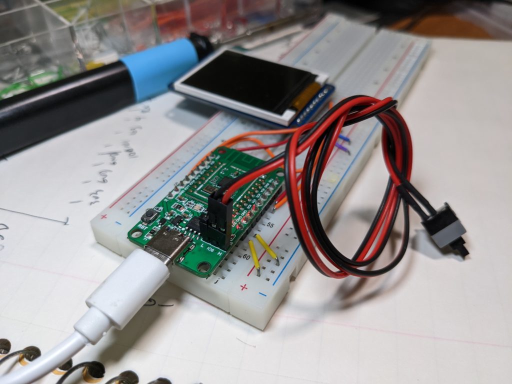
The thing that’s harder to script is the amount of physical fiddling that’s required. You have to move a jumper on IO8 from L to H, press the reset to start the board’s native code downloader, then move the jumper back and press the reset again. It’s very easy to miss one of those steps while debugging a binary, so you end up looking at the source for version N, but running version N-1 on the device. As you can guess, it’s frustrating.

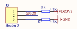
I’ve long had it in my mind that the jumper was a pin on the address bus and the CPU needed to be connected to one block to program it and another to run it. (That sounds wrong now that I’m typing that, but I have had hardware in my past that required this.) The schematic for the Pine64 board is dead simple as all the ‘magic’ is in the canned castellated board.

There is no magic to this pin. This pin is connected to GPIO8 on the BL602. The state of GPIO8 is polled exactly once in the bootup sequence. Though there are pullups via the jump to high or low, the pin floats in the ‘low’ state, which allows the device to boot to the flashed code by default. So if you just remove the jumper, the board runs the last code you squirted into it. That seems a nice default. How can we use this to our advantage?

What if we scavenged a momentary contact switch for this? PC power supplies haven’t had “real” power buttons in decades. There’s a momentary pushbutton that sends a request to the power supply to kindly turn off or on, based on the momentary push of a button that just usually happens to feel clicky. They usually just happen to have a header that’s on .100 posts, so they’ll just slide right on.

With this “hack” in place (“Number 143 will blow your mind!”) resetting the board can become a fluid motion that you can commit to muscle memory:

  1. Press and hold your newly attached button.
  2. Press the reset button.
  3. Release the reset button.
  4. Release your new ‘boot button’.
  5. Start your code download.
  6. Press the reset button to begin running your code

It’s probably possible to release the button too fast as several opcodes have to be executed to configure the processor and ultimately poll that button, but it’s my experience that as long as you treat it Press A-B Release B-A, it’ll come up executing the downloader every time. 

Also, to summarize the key parts of the BL engineering spec for the bootloader, it’s helpful to recognize the boot flow.

  1. Reset Vector -> chip setup -> check GPIO 8. Is it low? Jump to user code. Else, start bootloader.
  2. The bootloader will start spraying ‘.’ (period) character while it’s listening to the serial port. These are at 2,000,000 bps by default. This is unfortunate because it’s a high enough rate that many programs can’t listen at this spec. I’ve not counted them or put them on a scope, but I’d say there are 8-10 of these a second.
  3. Inside this same loop, it’s also listening to the serial port. If it receives a ‘U’ (0x55 – chosen to maximize bit toggles so it can sample widths) it will try to reset the serial bit rate to match that speed and the ‘.’ pattern will continue at the new rate. Depending on exactly when that ‘U’ is received, it may take a couple of these to sync up at another bit rate.
  4. Now that the initial bit rate has been agreed upon, a program like blflash can do “protocol stuff” (documented elsewhere) to send the download to the BL device.

If you’re running a program like CoolTerm to actually talk to the device, it’s useful to set it at the matching bitrate. You’ll know you’ve missed a step if  you see the streaming period characters because that means the device is listening to you typing, awaiting “protocol stuff” packets, instead of the upload program, like blflash. Starting and stopping (‘connecting’ and ‘disconnecting’ in CoolTerm) the application you may be viewing the serial port is another step to synchronize with this. It’s for this reason you should try to quickly get your app to a state where it can communicate via a screen or blinking lights just so you don’t have another step. That’s just an unfortunate reality of hardware makers giving us one port to use as both code uploader and as console.

Enjoy jumper-free life!

P.S. just attach it with one leg dangling free so you’re less likely to lose it.

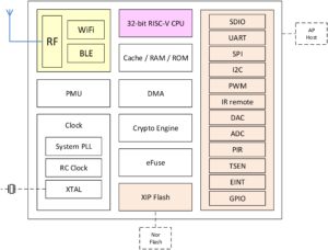
I normally don’t do “scoops”, but as I write this, I can find no other pages on Google in English mentioning the Bouffalolabs BL562 and BL564 RISC-V chips. Even Bouffalab’s own page is pretty scant right now. (I’m writing this late on 2021-03-31 and no, this isn’t April fool. Maybe it is and I’ve fallen for it, but it seems terribly non-funny…) However, this seems like a very interesting contender in the low-power RISC-V processor market. It’s very likely a subset of the already-successful BL602/BL602, but without the 2.4Ghz radios that give it WiFi or Bluetooth.  This also means the parts of the chip that have the most contentious NDA requirements for certification are simply not there.

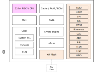
Comparing Boufallolab’s own overview sheets of the BL562/4 and BL602/4 really highlights that only the yellow block, the RF radios, are different. The pin counts are the same as BL602/4, with at 32 or 40 pin QFN packages. It’s very likely the same RISC-V core running at speeds up to 192Mhz and with 276KB of RAM and 128KB of flash ROM.

It seems likely they’re pin-compatible, but we don’t yet have specification sheets with that level of information that I can find.

BL602 is already a price leading choice for low-end designs, with single-piece pricing of about $1USD. It’s easy to imagine that bulk orders can reduce by that a third or more. We can probably look to the BL602 for real-world performance measurements. The clock speed over the 108Mhz Gigadevices GD32VF103 family has given it a hand up in my own measurement. (I don’t have formal numbers.) GD32V, probably the most natural device to compare these two, ships in QFN36, LQFP48, LQFP64, and LQFP100 packages, so it has more I/O, notably USB support, which is absent in BL562.

This entry is a bit of a surprise as the medium (“runs Linux”) and high end(“runs a graphical desktop”) developments in RISC-V have been much publicized, it’s important to remember that not everything is IoT or needs to be able to render Netflix at 4K. With a smaller size, lower pin count, we score another gain of modernization. While GD32V’s 32K (max – there are smaller ones) of memory can feel a bit cramped, the 276KB of RAM may feel downright luxurious in some designs.

BL562

General purpose RISC/V SoC

BL602/604

RISC-V core with 802.11 and Bluetooth

As a general-purpose RISC-V processor, this is sure to score some commercial design wins where pennies count and hobby interest, where good development tools matter. Bouffalo Labs, in cooperation with SiFive, have an established SDK that’s been picked up by Pine64  and SeedStudio.  There has been some jockeying lately at high-end hobbyist or media-player class devices, so it’s refreshing to see another player come back, wearing a slightly different costume, with a solid part in the dollar (or less?) market that’ll keep our rectangles blinking.

Assuming it’s the same RISC-V core (surely!) as Bl602, it’ll build on the established SDK provided by Boufallo and forked by Pine64 for their  PineCone and PineNut lines and by Sipeed for their BL602 product and DoIt for DT-BL10.

Epilogue

Is it a scoop? I don’t really care. I’m always astonished how quickly things get to the likes of CNX, Reddit’s/r/risc-v, and the Twitter buzz. There is, of course, the time dilation between tech in China and the Western World. I was clicking around on Boufallo’s site, trying to find information on yet another part, and fiddled with the URL when I landed on BL-562.

At least for some short time, I think I have a reasonable claim on “first” and maybe even “most comprehensive”. 🙂

We’re all familiar with the fable of the boiling frogs, unable to sense the change they’re (literally!) immersed in. Enthusiasts of RISC-V architecture may be encountering the same right now: late 2020 gave us a steady stream of new hardware announcements, but we may not have a great sense of us since the hardware isn’t always possible to order yet. Let’s review some of the upcoming products in this market, duly nothing that products can change or get canceled before they even ship.

We had two major new families of entries in the iOT category. Both use the RISC-V to drive WiFi and Bluetooth radio stacks. Bouffalo Lab’s BL602 is available in quantity now. Starting around $2.50 for a module with multiple development boards in the $5-$10 range (including Pine64’s Nutcracker for PineCone and the DoIt DT-BL10), this chip starts with a core from SiFive and has 802.11 b/g/n and Bluetooth 5. The upcoming BL-702 family adds Zigbee radios. There is enough compute resources (CPU, RAM, Timers, etc.) that you can build your own software right onto the radio chip via their multitasking OS and open development kits. You may recognize this as the basic model popularized by Espressif in their ESP8266 in recent years.

Espressif also embraced RISC-V with their upcoming ESP32-C3 family. It’s interesting that this chip doesn’t even get a distinct name at this point as Espressif apparently sees the CPU core as only a small part of the product. Still, by volume, the ESP32-C3 is likely to become an extremely popular choice.

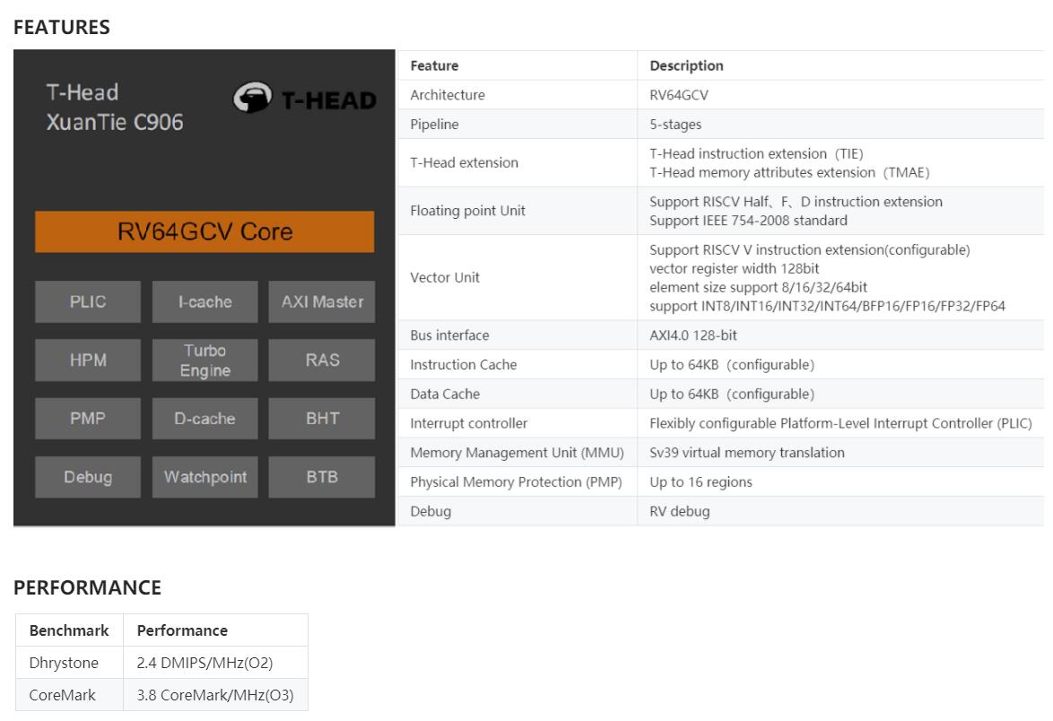
Moving up a step computationally, we enter more traditional chips and single-board computers. Alibaba’s Xuantie 910 is widening into a family of chips. The C906 is being marketed for more entry level class, but still featuring a load of I/O, multiple cores, support for the still-not-ratified Vector extensions, and more. Press releases tend to mix up the 910 and the 906, but they both seem pretty hot.  In late January, anAndroid Open Source Port of C910 was demonstrated. Embedded specialists Sipeed have announced a C906 development board that’ll run Debian and that starts at $12.50. If Sipeed does for that what they’ve done for GD32V and K210, we should see lots of interesting SBC projects from them.

Sipeed teases C906 RISC-V board

Rios is bringing us a claimed competitor to the Raspberry Pi called the PicoRio. It’s coming inthree stages:

  • PicoRio 1.0 is a headless, four-core RV64GC that’s capable of running Linux at 500Mhz. It’s been used from 2020H2 to an expectation of beta in 2021H1.
  • PicoRio 2.0 adds Imagination’s PowerVR GE7800 XE series GPU, which may finally bring a GPU-capable RISC-V development board into casual hobbyist price points.
  • PicoRio 3.0 strives to bring the performance to be comparable to a tablet or desktop computer.

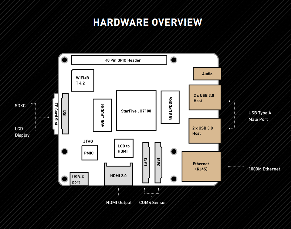
Another entry in the Pi-class of hardware, though not at Pi Price, is the Beagle V from the group that brought us the famed Beagle Bone. It uses two of SiFive’s U74 cores at 1Ghz includes 8GiB of LPDDR4 RAM, gigabit Ethernet, an 802.11n Wi-Fi + Bluetooth 4.2 chipset, and a dedicated hardware video transcoder supporting H.264 and H.265 at 4K and 60fps.The system also offers four USB 3.0 ports, a full-size HDMI out, 3.5mm conventional audio jack, and a 40-pin GPIO header. As a snack for those interested in AI applications, it also features  a Tensilica Vision VP6 DSP for machine-vision applications, a Neural Network Engine, and a single-core NVDLA (Nvidia Deep Learning Accelerator).

Core provider SiFive is bolting Freedom U740 cores to a min-ITX design in HiFive Unmatched. X16 PCIe expansion, 16GB of DDR4 RAM, NVME M.2 slot, Gigabit ethernet, and four cores at 1.4Ghz should make this a entry-level desktop-class system, including host-CPU class of building for native applications at full scale. For professional developers, the $665 entry ticket should be more appealing that the $999 for the board’s predecessor, Unleashed.

The PicoRio V1 and Unmatched have already slipped from Q4 into 2021.

Still, while we’re not bathing in fresh alternatives to the GD32V and K210, we have several alternatives on the proverbial launching pad and several options to bring excitement into lives and toolboxes of RISC-V aficionados.

What do you see coming up? What are you most anxious to work with?


I haven’t talked much about it (this being my first post and all…) but I’m pretty smitten with the current wave of RISC-V processors. I really like that it’s an open development platform, which means chip companies can buy or create the core that works with the basic instruction set and the programmers have a consistent and shared set of tools for the entire line ranging from $.10 parts for a home thermostat to a workstation class part. Rising tides and all that.

As a software guy, there are chip vendors that I’ve never heard of, but Bouffalolab Lab seems to be a pretty new name to most of us in the U.S. They’re making waves with the announcement of the BL602 and BL604 Systems-on-Chip (SOC). This part is just becoming available in the final week of October 2020 and it’s looking pretty interesting.

There are two parts in the immediate family: the BL602 and the BL604. The two parts differ by the number of GPIO pins and thus, the size of the external package. BL602 has 16 GPIOs and comes in a 32-pin QFP. The BL604 bumps to 23 GPIOs and rides in a 40-pin QFP. The 32-pin part should come in around 5mm per edge, so it’ll fit in really small applications. The integration is high enough that on the 32-pin part, half the pins are devoted to GPIO with the rest being the mandatory 3.3V, ground, crystal in, grounding, and other housekeeping. Outside the party, but similar enough that the SDK references them sometimes by accident, in the BL606 and 608. On those you go to ARM cores and trade wireless for audio, but that’s not our focus today.

It has 2.4Ghz radios, so that covers BTLE 5.0 and 802.11 b/g/n. Wi-Fi through WPA3 is supported. The microprocessor core runs at 192Mhz and comes from the SiFive cores. JTAG support is included and it claims support for the Segger family of debugging pods and software. It has 276K of SRAM, which is a really nice step up from the closest competing part, the GD32V’s which pack a mere 32K. Both parts have 128K of flash. There are two UARTs, but no USB controller like the GD32V. It has the standard alphabet soup that we expect in a post ESP8266 including SDIO, SPI, I2C, and such.

Bouffalo is a Chinese company and the documentation reflects that. Google Translate helps bring the doc and some code comments to us, but the reality is that many, many sections in the manual are just blank for now. The 34 page datasheet is oriented toward hardware developers, but does throw the smallest of bones to programmers. For example, it doesn’t tell you WHAT the UARTs are (it’s not a 16554) but it tells you where they are in memory.

A few companies are racing to put boards in the hands of developers. Both SiPeed and Pine64 seem to be early movers with prices hovering around $5USD with shipping being about as much again. I’m sure we’ll see an ocean of reference designs on Aliexpress and such soon. Currently, we have three such boards:

  • Pine64’s PineCone64: USB-C (yay!) via a CH340N and with RGB LED.
  • Doi.am’s DT-BL10: Micro USB
  • SiPeed’s BL602: Micro USB. Rumored to have FTDI serial interface. Might be same as Doi.am’s

Development environments include Eclipse + OpenOCD or Freedom Studio + OpenOCD. The company provides an app called DevCube (unrelated to the VR tool of the same name) to configure devices for production. This helps IoT makers prepare the flash for partitioning and OTA upgrades. It seems inevitable that the popular PlatformIO IDE will be supported. Since it’s a familiar SiFive core, just submitting the needed flash layout and programming data is probably on the order of dozens of lines of code to support PlatformIO for BL602/BL606.

If we look past the large number of blank doc pages and the high percentage of Chinese in the SDK, what do we find? This is actually the jackpot for RISC-V designs – there are working Mac, Linux, and Windows (Cygwin) GNU-based toolchains right in the tree at launch. Filenames are a bizarre mix of CamelCase and underscore_separators, even sometimes in the same directory. It ships with GCC 8.3, but since RISC-V was upstreamed a while ago, I’d expect upgrading to later versions to be easy. It relies heavily on Amazon’s FreeRTOS as the core. The entire package relies on external source (FreeRTOS, GNU Tool binaries, compression libs, etc.) by copying and not via git-referencing the modules by inclusion. This means you’re probably always on a stable build, but it also almost insures that you’ll always be behind releases of third party code, which can be bad in network-connected devices.  Amazon’s MQTT and Jobs interfaces are well represented. The expected libraries for a high-functioning 32-bit core are all there, with a pretty full ANSI libc with printf, compression and a filesystem for the flash. Startup code is a pretty straight SiFive example for GCC. There are 31 separately buildable apps for demonstrating features of the device, including a CLI for interfacing with it somewhat like boot monitors of days past. “Hello, World” is there, of course, but ironically doesn’t contain the string “hello” as it gets printed in a callback from the initialization state machine as it advances.

The network modules are, unfortunately, binary blobs at this time. I expect the community to make short work of changing that.

Overall, this looks like a good entry for the bottom/low-end space for wirelessly connected (or not) devices for hobbyist and commercial applications. The SiFive core is well regarded for performance and the performance should be better than the GD32V’s 108Mhz while the price lower than the AI-centric dual-core 64-bit Kendryte K210.

Start your engines with:

Official Boufallo SDK
Pine64 is offering hardware to developers that help get BL602 started.
SiPeed (makers of Longnan and Maix lines) has a BL602 SDK.
Doit has a $4 eval board with a BL602 SDK.
All three of those are forks from the Boufallo code. We don’t know yet how different the hardware is.

RJL