I’ve seen variations of these products from China for months, but finally saw an offer I could only reluctantly refuse. Amazon had the AIPI-Lite AI Robot for about $17USD. (https://www.amazon.com/dp/B0FQNNVV36). A battery adds another $10. (“Battery not included”. Grrr.) That’s within range for my toy budget, so I was determined to take it apart. I may or may not get anywhere with it, but I thought I’d put any notes I made so I can find them later, so I’m going to put them right here in plain sight of Google so I can “just Google it”. Perhaps if you have any findings, I hope you can share therem here, too.
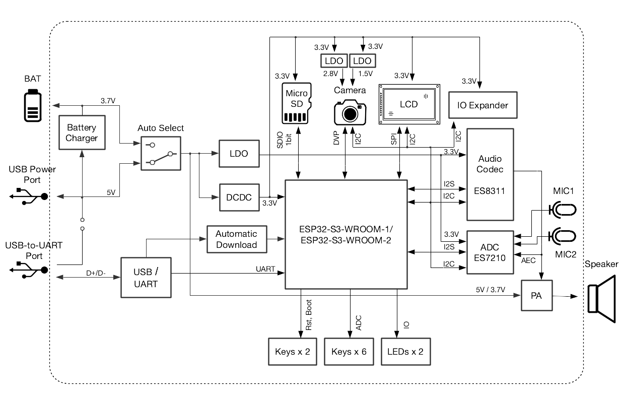
The core of the hardware is an ESP32-S3 with a 128×128 screen. We can deduce it uses WiFi, as that’s part of the Espressif ESP32-S3 System On Chip. We know there’s a battery, mic, audio amp and such. We’ll get to those. From just those specs, my fellow electronics nerds ethusiasts can probably fast forward a chapter or two on my thinking: it’s likely pretty self-evident how these work as it’s probably electronically similar to an M5Stack CoreS3 or an Espressif S3-Box.
The ESP32-S3 chip provides a powerful 240Mhz, dual-core CPU with some opcodes that help with convolution and other AI-ish things that would help with speech recognition, so it’s able to route the spoken audio to the ESP32-S3. SPI displays are pretty easy with just a few pins for clock, data, chip selects, and backlights – a logic analyzer will pretty quickly tell us which is which. It will tell us… This class of device often ships your request off to the cloud, waits for a reply comes back, it splashes some words on the screen and ships some data to the audio amp for the speaker to respond. A little battery logic to stop the USB port from cooking the Li-Ion batter and we’ve got the block diagram largely locked.
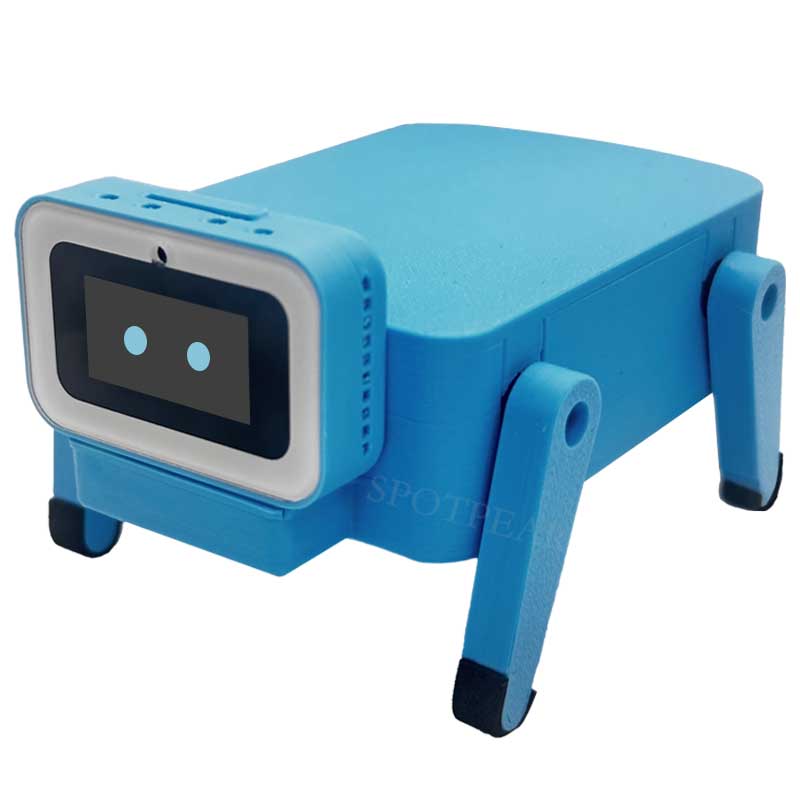
Before the Amazon Fairy even arrives, we can speculate it looks pretty much like a cost-reduced (minus camera, minus keys) ESP32-S3 Korvo:
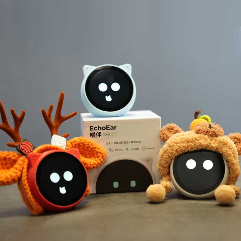
In my earlier cruising of Chinese sites, I suspected they probably all have an extremely schematic, if not identical, and there’s probably only a few companies that make them just with different plasticware around them. So if you wanted one that looked like a giant eyeball, but your sister wanted one that looked like a cat and your brother wanted one that looked like a pig, they could cover them all. Maybe there’s some variation in touch screen or quality of audio or size of battery, but the hard part should all be the same, right? Now it’s easy to imagine a device that’s the same, but different, looking like any of these:
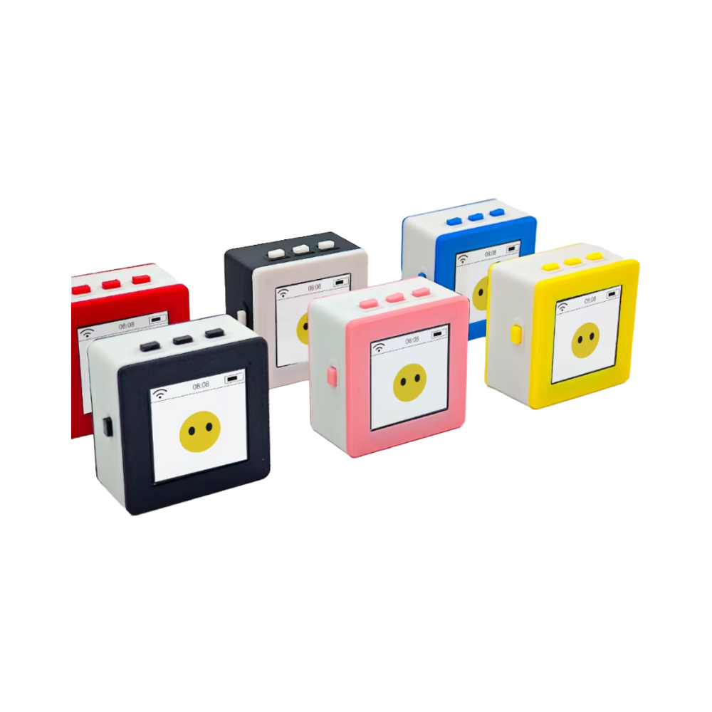
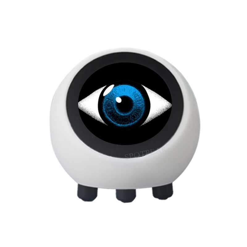
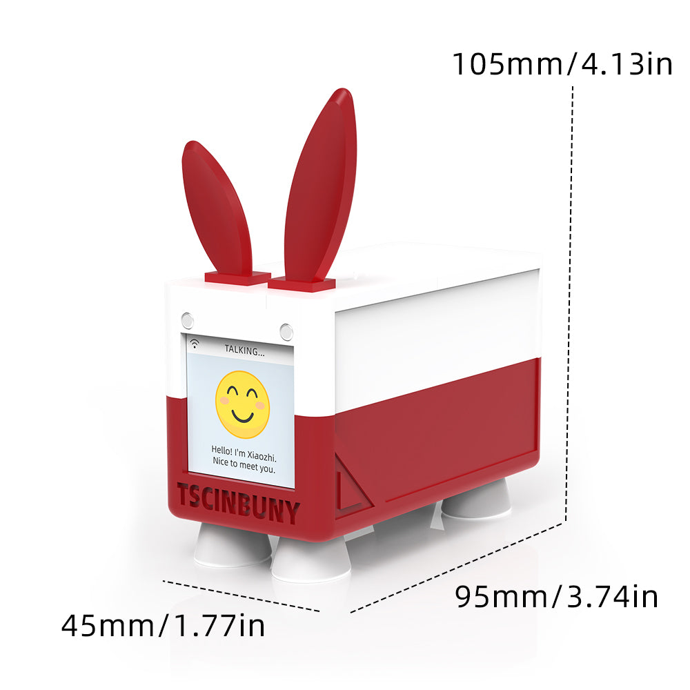
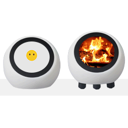
As a sidebar,I know that Chinese culture is quite different and I’ll try not to judge, many of the plastic figures seem oriented to children to me. These are sold on Amazon under “Toys and Games category. Sure, the pictures are of Grandma remembering a lost Grandpa, Hunky Dad on beach that’s forgotten Wifey’s birthday, and Creepy Dude Totally Not Making A Robot Grandpa, but a cat, a pig, and a giant eye seems that these are very much made for kids. I’m not totally how this sits with the Child Online Privacy Protection Act (COPPA) in the U.S. that “protects the online privacy of children under 13 by requiring website operators and online services to obtain verifiable parental consent before collecting, using, or disclosing personal information from them.” Once these are configured and given to a child, the ship somewhat sails on what the child will say to the AI and what the AI will say to them. I suppose that “verifiable parental permission” is covered by NOT accidentally buying one of these and NOT accidentally configuring them for WiFi.
The Amazon fairy delivered. Initial setup was a bit frustrating mostly because I ran ashore of the instructions while the unit would shout out a six digit number once or twice a minute, with no ability to hush it and no way to turn the volume down. It took embarrassingly long for me to realize that just separating the batery pack was a sure thing. Can’t shout at me without electrons! Neener Neener!
Time to poke at it in earnest with some intent to reverse engineer it. Out come the software torture tools of the trade. The first order of business is to confirm exactly what chip is in it. The easiest way to do that is to just ask it.
$ esptool -p /dev/cu.usbmodem31101 chip-id
esptool v5.0.1
Connected to ESP32-S3 on /dev/cu.usbmodem31101:
Chip type: ESP32-S3 (QFN56) (revision v0.2)
Features: Wi-Fi, BT 5 (LE), Dual Core + LP Core, 240MHz, Embedded PSRAM 8MB (AP_3v3)
Crystal frequency: 40MHz
USB mode: USB-Serial/JTAG
MAC: 98:a3:16:c9:e4:4c

Stub flasher running.

Warning: ESP32-S3 has no chip ID. Reading MAC address instead.
MAC: 98:a3:16:xx:xx:xx (I'm probably going to forget to hide this everywhere...)

Hard resetting via RTS pin...
Well, that’s comforting – the chip is NOT encrypted and secure boot is disabled!
This is really promising for hacking. Let’s make a copy of the contents of flash. I didn’t think to do this before I configured my WiFi, so I’m not going to provide my copy, but you can make your own. We know flash starts at 0 and if you have 16Mb, that’s 0x40000, so…
$ esptool -b5000000 -p /dev/cu.usbmodem31101 read-flash 0 0x400000 original.bin
esptool v5.0.1
Connected to ESP32-S3 on /dev/cu.usbmodem31101:
Chip type: ESP32-S3 (QFN56) (revision v0.2)
Features: Wi-Fi, BT 5 (LE), Dual Core + LP Core, 240MHz, Embedded PSRAM 8MB (AP_3v3)
Crystal frequency: 40MHz
USB mode: USB-Serial/JTAG
MAC: 98:a3:16:c9:e4:4c

Stub flasher running.
Changing baud rate to 5000000...
Changed.

Configuring flash size...
Read 4194304 bytes from 0x00000000 in 47.0 seconds (713.3 kbit/s) to 'original.bin'.

Hard resetting via RTS pin...
Now if we mess things up, we should have a copy of all of the contents of flash if things go awry. This ensures a recoverable state before any modifications. Depending upon the USB configuration, it may or may not be easy to recover from that, but at least we have running code image before we clobber it. We will clobber it…
Firmware Content Analysis
Let’s see what’s inside the firmware image.
$ strings original.bin | head
v5.3.2-dirty
May 23 2025 14:34:10
Assert failed in %s, %s:%d (%s)
abort() was called at PC 0x%08x
load_end > load_addr
//IDF/components/bootloader_support/src/esp_image_format.c
end1 > start1
//IDF/components/bootloader_support/include/bootloader_util.h
Calculated hash
Expected hash
There’s no reason for me to include everything from the binaries, but there’s definitely enough recognizable strings in there in cleartext (including my Wifi credentials. :-/) to feel pretty good about this.
Let’s use our knowledge of the ESP32-S3 that most of them present a debug console on the serial port’s that echoed to the USB connection over a CDC/ACM emulation of a serial port. Let’s see if we can repeat our encouraging start.
Boot to Wifi Configuration.
Leveraging the ESP32-S3’s debug console via its USB serial connection, I observed the boot process during Wi-Fi configuration. Key log entries, using Google Translate to translate the Chinese to English and then annotated with “RJL”, highlight the device’s initialization:
I (449) CustomPM: 进入开机状态 - RJL Enter power-on state
I (489) CustomPM: 进入开机状态 - RJL Enter power-on state
I (489) YuanZhiESP32S3: power on
I (489) uart: queue free spaces: 20
I (489) FactoryTask: UART driver installed and configured for port 1.
I (489) FactoryTask: FactoryTask initialized successfully.
I (499) FactoryTask: UART event task started.
I (499) FactoryTask: UART event received. Type: 1, Size: 0
W (509) FactoryTask: UART RX break
I (509) FactoryTask: Command parser task started.
I (519) FactoryTask: Factory task processing started.
I (529) gpio: GPIO[5]| InputEn: 1| OutputEn: 1| OpenDrain: 1| Pullup: 1| Pulldown: 0| Intr:0
I (539) gpio: GPIO[4]| InputEn: 1| OutputEn: 1| OpenDrain: 1| Pullup: 1| Pulldown: 0| Intr:0
I (549) gpio: GPIO[7]| InputEn: 0| OutputEn: 1| OpenDrain: 0| Pullup: 0| Pulldown: 0| Intr:0
I (549) gpio: GPIO[18]| InputEn: 0| OutputEn: 1| OpenDrain: 0| Pullup: 0| Pulldown: 0| Intr:0
I (679) Display: Power management not supported
I (699) LcdDisplay: Turning display on
I (709) LcdDisplay: Initialize LVGL library
I (709) LcdDisplay: Initialize LVGL port
I (709) LVGL: Starting LVGL task
I (709) LcdDisplay: Adding LCD screen
I (729) LcdDisplay: DisplayNotification: Creating Notification_t for 'no_str', duration: 2000 ms, icon: 'Starting'
I (749) Notification_t: Creating: 0x3fcd45ac, Initial Text: 'no_str'
I (969) CustomPM: 已设置长按5秒NVS标志位为: 0
I (969) Backlight: Set brightness to 50
I (969) YuanZhiESP32S3: ======= 开始状态仲裁 ======= RJL Starting state arbitration
I (969) YuanZhiESP32S3: 输入 - 电源状态: 7, 设备状态: 0 - RJL Input - Power state: 7, Device state: 0
I (979) YuanZhiESP32S3: 全局最高优先级状态: PowerState, 值: 7, 优先级: 5 (数字越小优先级越高) - RJL Global highest priority state: PowerState, value: 7, priority: 5 (the lower the number, the higher the priority)
I (989) CustomPM: 充电完成,进入满电状态 - RJL Charging completed, entering the full power state
I (989) Application: STATE: starting
I (999) Es8311AudioCodec: Duplex channels created
E (1009) i2c.master: I2C transaction unexpected nack detected
E (1009) i2c.master: s_i2c_synchronous_transaction(892): I2C transaction failed
I (1019) gpio: GPIO[21]| InputEn: 1| OutputEn: 0| OpenDrain: 0| Pullup: 0| Pulldown: 1| Intr:1
I (1029) CHRG_INIT: CHRG pulse counter initialized on GPIO 21
E (1029) i2c.master: i2c_master_transmit(1133): I2C transaction failed
E (1039) I2C_If: Fail to write to dev 30
I (1049) ES8311: Work in Slave mode
I (1049) gpio: GPIO[9]| InputEn: 0| OutputEn: 1| OpenDrain: 0| Pullup: 0| Pulldown: 0| Intr:0
I (1059) Es8311AudioCodec: Es8311AudioCodec initialized
I (1069) YuanZhiESP32S3: ======= 开始状态仲裁 ======= - RJL Start state arbitration
I (1069) YuanZhiESP32S3: 输入 - 电源状态: 7, 设备状态: 1 - RJL Input - Power state: 9, Device state: 1
I (1079) YuanZhiESP32S3: 全局最高优先级状态: DeviceState, 值: 1, 优先级: 2 (数字越小优先级越高) - RJL Global highest priority state: DeviceState, Value: 1, Priority: 2 (smaller numbers have higher priorities)
I (1089) Application: WiFi board detected, setting opus encoder complexity to 3
I (1099) YuanZhiESP32S3: ======= 开始状态仲裁 ======= - - RJL Start state arbitration
I (1099) YuanZhiESP32S3: 输入 - 电源状态: 9, 设备状态: 1
I (1109) YuanZhiESP32S3: 全局最高优先级状态: DeviceState, 值: 1, 优先级: 2 (数字越小优先级越高) - Global highest priority state: DeviceState, value: 1, priority: 2 (the lower the number, the higher the priority)
I (1119) CustomPM: CHRG pulse count: 8
I (1129) YuanZhiESP32S3: button block
I (1129) PowerSaveTimer: SetEnabled: 0
I (1139) OpusResampler: Resampler configured with input sample rate 24000 and output sample rate 16000
I (1149) OpusResampler: Resampler configured with input sample rate 24000 and output sample rate 16000
I (1159) I2S_IF: channel mode 0 bits:16/16 channel:2 mask:1
I (1159) I2S_IF: STD Mode 0 bits:16/16 channel:2 sample_rate:24000 mask:1
I (1169) I2S_IF: channel mode 0 bits:16/16 channel:2 mask:1
I (1179) I2S_IF: STD Mode 1 bits:16/16 channel:2 sample_rate:24000 mask:1
I (1199) Adev_Codec: Open codec device OK
I (1199) AudioCodec: Set input enable to true
I (1199) I2S_IF: channel mode 0 bits:16/16 channel:2 mask:1
I (1199) I2S_IF: STD Mode 1 bits:16/16 channel:2 sample_rate:24000 mask:1
I (1219) Adev_Codec: Open codec device OK
I (1219) AudioCodec: Set output enable to true
I (1219) AudioCodec: Audio codec started
I (1219) Application: STATE: configuring
I (1229) CustomPM: 已设置长按5秒NVS标志位为: 0
I (1239) YuanZhiESP32S3: ======= 开始状态仲裁 =======
I (1239) YuanZhiESP32S3: 输入 - 电源状态: 9, 设备状态: 2
I (1249) YuanZhiESP32S3: 全局最高优先级状态: DeviceState, 值: 2, 优先级: 4 (数字越小优先级越高)
I (1259) DnsServer: Starting DNS server
I (1259) pp: pp rom version: e7ae62f
I (1269) net80211: net80211 rom version: e7ae62f
I (1279) wifi:wifi driver task: 3fce23a0, prio:23, stack:6656, core=0
I (1289) wifi:wifi firmware version: b0b320f
I (1289) wifi:wifi certification version: v7.0
I (1289) wifi:config NVS flash: enabled
I (1289) wifi:config nano formating: disabled
I (1299) wifi:Init data frame dynamic rx buffer num: 32
I (1299) wifi:Init dynamic rx mgmt buffer num: 5
I (1299) wifi:Init management short buffer num: 32
I (1309) wifi:Init static tx buffer num: 16
I (1309) wifi:Init tx cache buffer num: 32
I (1319) wifi:Init static tx FG buffer num: 2
I (1319) wifi:Init static rx buffer size: 1600
I (1329) wifi:Init static rx buffer num: 16
I (1329) wifi:Init dynamic rx buffer num: 32
I (1329) wifi_init: rx ba win: 16
I (1339) wifi_init: accept mbox: 6
I (1339) wifi_init: tcpip mbox: 32
I (1349) wifi_init: udp mbox: 6
I (1349) wifi_init: tcp mbox: 6
I (1349) wifi_init: tcp tx win: 5760
I (1359) wifi_init: tcp rx win: 5760
I (1359) wifi_init: tcp mss: 1440
I (1369) wifi_init: WiFi/LWIP prefer SPIRAM
I (1369) wifi:Set ps type: 0, coexist: 0

I (1369) phy_init: phy_version 700,8582a7fd,Feb 10 2025,20:13:11
I (1409) wifi:mode : sta (98:a3:16:c9:e4:4c) + softAP (98:a3:16:c9:e4:4d)
I (1409) wifi:enable tsf
I (1409) wifi:Total power save buffer number: 8
I (1419) wifi:Init max length of beacon: 752/752
I (1419) wifi:Init max length of beacon: 752/752
I (1429) WifiConfigurationAp: Access Point started with SSID PI-Lite-E44D
I (1429) esp_netif_lwip: DHCP server started on interface WIFI_AP_DEF with IP: 192.168.4.1
I (1439) WifiConfigurationAp: Web server started
W (1449) Application: Alert Wi-Fi Configuration Mode: 1.Hotspot: PI-Lite-E44D
2.Config URL: http://192.168.4.1
3.Select WiFi and enter the password
[]
I (1459) Application: Resampling audio from 16000 to 24000
I (1469) OpusResampler: Resampler configured with input sample rate 16000 and output sample rate 24000
I (1479) WifiBoard: Free internal: 37043 minimal internal: 36827
E (1719) Application: Protocol not initialized
I (2749) Notification_t: Destroying: 0x3fcd45ac, Text: 'no_str'
I (2749) LcdDisplay: NotificationTimerCallback: Timer object 0x3fcd8ae8 deleted successfully.
I (2759) LcdDisplay: DisplayNotification: Creating Notification_t for '1.Hotspot: PI-Lite-E44D
2.Config URL: http://192.168.4.1
3.Select WiFi and enter the password
', duration: -1 ms, icon: 'Configuration'
I (2779) Notification_t: Creating: 0x3fcd45ac, Initial Text: '1.Hotspot: PI-Lite-E44D
2.Config URL: http://192.168.4.1
3.Select WiFi and enter the password
'
I (2799) LcdDisplay: DisplayNotification: For permanent '1.Hotspot: PI-Lite-E44D
2.Config URL: http://192.168.4.1
3.Select WiFi and enter the password
', _notification_timer_ is now 0x0.
I (11479) WifiBoard: Free internal: 40871 minimal internal: 36791
I (21479) WifiBoard: Free internal: 40871 minimal internal: 36635
These last few lines repeat. It’s common for embedded to juse do a little hearbeat like this.
Let’s see what the “real” firmware looks like when running:
{
    "version":	2,
    "language":	"en-US",
    "flash_size":	16777216,
    "minimum_free_heap_size":	8279036,
    "mac_address":	"98:a3:16:c9:e4:4c",
    "uuid":	"ca444c6e-a69b-4e84-909f-de5f849b6724",
    "chip_model_name":	"esp32s3",
    "sn":	"XY006PL01USA0202775",
    "chip_info":	{
        "model":	9,
        "cores":	2,
        "revision":	2,
        "features":	18
    },
    "application":	{
        "name":	"xiaozhi",
        "version":	"1.1.3",
        "compile_time":	"Sep 15 2025T20:42:53Z",
        "idf_version":	"v5.3.3-dirty",
        "elf_sha256":	"ac436cad8f0e0e1ad920200416fed482dd3f0cd7ae0c91772dfb889814b40c25"
    },
    "partition_table":	[{
            "label":	"nvs",
            "type":	1,
            "subtype":	2,
            "address":	36864,
            "size":	16384
        }, {
            "label":	"otadata",
            "type":	1,
            "subtype":	0,
            "address":	53248,
            "size":	8192
        }, {
            "label":	"phy_init",
            "type":	1,
            "subtype":	1,
            "address":	61440,
            "size":	4096
        }, {
            "label":	"model",
            "type":	1,
            "subtype":	130,
            "address":	65536,
            "size":	983040
        }, {
            "label":	"ota_0",
            "type":	0,
            "subtype":	16,
            "address":	1048576,
            "size":	6291456
        }, {
            "label":	"ota_1",
            "type":	0,
            "subtype":	17,
            "address":	7340032,
            "size":	6291456
        }],
    "ota":	{
        "label":	"ota_1"
    },
    "board":	{
        "type":	"xuanzhi-yuanzhi-esp32s3",
        "name":	"xuanzhi-yuanzhi-esp32s3",
        "ssid":	"RJLs-iot",
        "rssi":	-34,
        "channel":	11,
        "ip":	"192.168.2.207",
        "mac":	"98:a3:16:c9:e4:4c"
    }
}
This JSON provides a wealth of information, including firmware version (1.1.3), flash size (16MB), MAC address, chip model (ESP32-S3 with 2 cores), application name (“xiaozhi”), compile time, and partition table details. The MQTT and WebSocket configurations also reveal the cloud communication endpoints.
I (5229) MQTT: decrypted password: – RJL BIGNUMBER
{
    "firmware":	{
        "version":	"1.1.3",
        "url":	""
    },
    "mqtt":	{
        "endpoint":	"152.32.151.73",
        "port":	"1883",
        "username":	"<meta charset='utf-8'>XY006PL01BIGNUMBER",
        "password":	"dfbf5fd174d8b97ba64b5caf0d5c47d47bc395a98e8d47825bdd86b6e81efef3",
        "client_id":	"<meta charset='utf-8'>XY006PL01BIGNUMBER",
        "publish_topic":	"xorigin/device-server/<meta charset='utf-8'>XY006PL01BIGNUMBER",
        "subscribe_topic":	"xorigin/devices/<meta charset='utf-8'>XY006PL01BIGNUMBER",
        "p2p_topic":	"forwards/p2p/<meta charset='utf-8'>XY006PL01BIGNUMBER/#"
    },
    "websocket":	{
        "url":	"ws://xdc-chat.xorigin.ai:8000/xiaozhi/v1/",
        "token":	"kaf7vNyM7beGyCoGyqa8VehFoUEXnsfuAS56Kt1lnU"
    },
    "server_time":	{
        "timestamp":	1759809947350,
        "timeZone":	"America/New_York",
        "timeZoneOffset":	0
    },
    "snStatus":	{
        "sn":	"OK"
    }
}
That’s a lot of words, but we’re really just looking to harvest hardware data from it now. What have we learned?
Key Discoveries
GPIO
5, 4, 7, 18, These are configured in a clump. The lines following this are Display this, LcdDisplay that, and LVGL the other. That’s a good hint. 5 and 4 are both in and out. 7 and 18 are output only. It’s PROBABLY SPI – most LCDs are. For such a small display, MISO is probably ignored and CS is probably tied. So we need SCK (clock), MOSI (Master out, slave in), D/C (Data/Command), and maybe Reset. Maybe. All these are configured as outputs, but 4, and 5 can be either. Brightness comes later, but not with debugging we can identify, but let’s leave 5, 4, 17, and 18 as LCD candidates.
21 “CHRG pulse counter initialized on GPIO 21”. There is a pulse counter on the ESP32. i haven’t used it, but know it’s there. It’s mentioned in the middle of ES8311 initialization, which doesn’t make sense. Since this chip usually takes I2C for commands and I2S for data, which requires more pins than that. But we know pin 21 is an input to the esp32. It’s Digital ONLY (as pulses would be)
9 We can see it’s an ouput and likely involves ES8311, but we don’t have much info yet
The device utilizes LVGL for its display interface and Opus for audio compression, converting analog mic input (via ES8311’s ADC) to I2S for the ESP32 before internet transmission.
CHIPS
We learned there’s an ES8311 “Low power mono audio CODEC”.
BUTTONS
If the designers read the Espressif design guidelines, the buttons would correspone to GPIO0 and CHIP_EN, but they don’t seem to act like those pins. Investigate more.
Mysteries
* The chip itself told us that it has “Embedded PSRAM 8MB”. It’s odd the chip doesn’t announce PSRAM as found. At runtime, it crows “17611” which isn’t a lot if you started out with 8*1024*1024, but maybe they have the system highly tuned and have everything preallocated from the beginning.
* “application”: “name”: “xiaozhi”, is likely a very strong hint.
* TOOD: XY006PL01BIGNUMBER is almost certainly a device S/N that was edited out
Next Steps
Disassembly, reassembly instructions, 50 high-resolution PCB images, and a deeper dive into the software ecosystem are planned.